

Handheld spot checks can miss pH changes during dosing and cooling. An online sensor shows the trend as the process runs and can support controlled adjustment. It is most useful when changes are fast or a missed deviation has significant consequences. For stable, low-risk batches, a suitable manual testing program may be enough.
1. What Does a pH Sensor Actually Do?
An industrial pH sensor measures acid-base conditions at its installed location. Connected to a suitable transmitter, it can provide a value for operators, alarms, batch trends, or an automated dosing sequence. The purpose is to make a process decision in time to act on it.
The basic loop is sensor → transmitter → controller → dosing pump. The controller compares the measured value with the target and makes a controlled addition. It then needs time for the addition to mix, react, and reach the sensor. A fast display refresh does not remove those delays.
The reading represents the whole batch only when the measuring point is representative. Keep manual reference checks where the product method or quality procedure requires them. Include the measurement and control scope in your cosmetic equipment buying guide before comparing quotations.
2. Which Products Require an Online pH Sensor?
Start with the process, not the product name. Ask how quickly pH changes, what happens if it leaves the acceptable range, and whether a reliable online measurement is practical. A product can require a pH test without requiring a permanently installed probe.
Cosmetic Products
Shampoo, body wash, cleanser, conditioner, and hair-color processes are common candidates. Continuous monitoring may help during acid-base adjustment or neutralization of a thickener. Water-containing AHA/BHA and vitamin C products can also need close pH control, depending on their formulation and process.
For creams, lotions, and sunscreen emulsions, use the defined product method. The relevant phase, sample preparation, temperature, and sensor response all matter. pH is one formulation parameter; it does not establish skin safety, preservation, SPF, or finished-product performance on its own. Our O/W versus W/O emulsion guide gives background on emulsion structure.
Pharmaceutical Products
Buffer preparation, aqueous gels, suspensions, and some disinfectant processes can benefit from online measurement. Assess ointments individually, especially anhydrous bases. Specify how the process reading relates to the approved laboratory method and product requirements.
Food and Beverage Products
Fermentation, sauces, and beverages may use pH as an important process indicator. Keep other required safety and quality controls in place. In vinegar production, pH and titratable acidity are different measurements; a pH reading does not replace the specified acid-content test. See the mayonnaise and salad-dressing production guide for the wider processing context.
Chemical Products
Neutralization, resin, latex, adhesive, detergent, and water-treatment dosing processes may need close pH control. Check the medium first: low conductivity, high solvent content, heavy fouling, or a limited water phase can make measurement difficult and affect sensor selection.
When You Don’t Need One
Keep manual testing when a suitable sampling method meets the process and quality requirements. This may apply to a stable formulation, small-batch development, or a low-risk process where changes between samples are unlikely to matter. Review the decision if the formula, scale, or control needs change.
For petroleum jelly, wax, lip balm, anhydrous creams, and silicone-oil formulations, a conventional direct aqueous pH reading is generally not meaningful. Follow any specified extraction or dilution method instead. Small-batch development also has its own trade-offs, covered in our laboratory mixing equipment guide.
Related equipment
- 500L liquid-soap and shampoo mixing machine — Example of a cleanser mixing application
- 1000L external-circulation emulsifying mixer — Example of a larger circulating process
- 5L laboratory circulation vacuum emulsifier — Example of a small development system
3. When Should pH Be Measured?
During Raw Material Addition and Neutralization
Use the signal once the probe is properly immersed, the medium is measurable, and mixing is sufficient. During charging or at a low fill level, a displayed number may not be fit for control. Build those conditions into the operating sequence.
During neutralization, feedback shows how the batch responds to each addition. Allow for mixing and sensor response before the next correction. Near a sensitive part of the neutralization curve, a small addition can produce a large change, so dosing strategy matters as much as the sensor.
During Cooling
Record pH together with temperature. A formulation’s actual pH can change as it cools or continues to react. Compare results at the temperature and preparation conditions defined by the product method. The steam versus electric heating guide helps frame the thermal cycle that the measuring assembly will experience.
Before Filling
Confirm the final batch condition using the agreed acceptance method. A demonstrated online method may support this check; representative laboratory or handheld testing may still be required. Use comparable sample preparation, temperature, and timing when investigating differences.
During CIP Monitoring
Rinse pH can help track removal of acidic or alkaline cleaning agents when the procedure and limits are established. It cannot show every product or detergent residue, and it does not prove that all equipment surfaces are clean.
Choose cleaning verification or validation methods for the residues and equipment involved. Direct surface checks or other justified analyses may be needed. Our CIP spray ball versus manual cleaning guide explains why neither a cleaning device nor one measurement establishes a complete cleaning process.
Related equipment
- 200L mobile heated homogenizing tank — Confirm normal processing and cleaning exposure separately when planning the probe
4. Choosing the Right pH Sensor
Glass Electrode vs ISFET
Glass electrodes offer established performance for many duties. ISFET sensors use a glass-free sensing principle and may suit applications where glass breakage is unacceptable. Compare the actual models for chemical compatibility, reference design, response, and cleaning resistance. Prevent contact with the agitator regardless of sensing technology.
Recommended Equipment
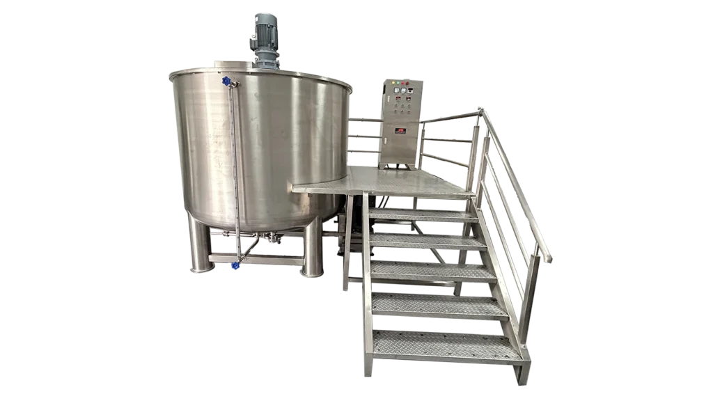
5000L Single Layer Homogenizer Mixing Tank for Liquid Soap, Detergent, Shampoo & Cosmetic Batch Production
View Details


Standard vs Hygienic
Select the whole assembly for the required hygiene level: probe, seals, port, housing, and cleaning access. A hygienic probe can still leave a poorly cleaned pocket if the adapter is unsuitable. Review the assembly using the hygienic design and surface-finish guide rather than relying on a general “food-grade” label.
Temperature Range
Choose an assembly rated for the highest temperature it will see, including cleaning and sterilization, as well as normal processing. Check duration, pressure, and cycling limits. Some probes allow a cleaning exposure outside their normal measurement range; confirm when their readings can be used.
Pressure and Vacuum Rating
Check the probe, housing, seals, and connection together. State whether pressures are absolute or gauge and include temperature-dependent limits. Confirm reference-system suitability for vacuum or pressure service, not just the rating printed on the vessel.
Chemical Compatibility
Review product, cleaning, and service fluids against every wetted material. Include the sensing surface, junction, body, and seals. Give the supplier concentrations, temperatures, and exposure times. The 304 versus 316L equipment material guide covers the wider equipment-material decision; the sensor needs its own compatibility review.
CIP/SIP Compatibility
Specify the actual time-temperature-pressure profile and cleaning chemistry. Avoid a generic “80°C CIP / 121°C SIP” requirement unless those are the approved project conditions. Confirm measurement validity during the cycle, control-inhibit requirements, and any post-cycle checks in the selected model’s instructions.
Signal Output
Separate the probe-to-transmitter connection from the transmitter-to-PLC interface. A conventional glass electrode generally needs a suitable high-impedance analyzer. System interfaces may include 4–20 mA, HART, Modbus, or compatible digital connections. Confirm scaling, temperature input, diagnostics, and fault behavior with the controls supplier.
Retractable Assemblies
A suitable retractable assembly moves the probe into an isolated service chamber. Removing the probe is a separate operation. Follow the assembly’s limits, isolation, depressurization, flushing, and interlocks. Whether production can continue—and whether a sterile boundary is maintained—depends on the installed design and approved procedure.
5. Where Should a pH Sensor Be Installed?
Agree the Position Before Fabrication
Agree the sensor port position with your supplier during design. It depends on vessel geometry, minimum working volume, baffles, agitator movement, and service access. Moving a port after fabrication can mean an avoidable repair and surface-treatment job.
Keep the Measurement Representative
Place the sensing surface and reference junction in well-mixed liquid throughout the approved batch-volume range. Check poorly swept outlets and pockets. Check flow at the vessel bottom and around baffles; each arrangement behaves differently. Assess circulation at the intended working volumes.
Use representative sampling or mixing trials where needed. The inner and outer circulation guide explains circulation arrangements; the cleaning dead corners guide looks at geometry that can retain product.
Avoid Dosing Plumes and Gas Pockets
A probe close to the dosing entry can see a concentrated addition before it reaches the bulk liquid. A poorly located distant probe can respond too late. Review circulation, injection position, mixing delay, and sensor response together.
Foam and gas bubbles can interrupt liquid contact at the measuring surface or junction. Keep the probe in the liquid, review aeration, and check installation orientation. For process sources of entrained air, see our guide to air bubbles in cream processing.
Prevent Mechanical Contact
Allow clearance from all moving parts, including lifting or retraction movements. Include tolerances and vibration. A guard may help if it remains cleanable and exposes the probe to representative liquid. An ISFET probe still needs protection from collision.
Follow the Model’s Orientation Requirements
A 45-degree side-wall position can work, but it is not a universal optimum. Follow the specified probe and housing orientation, insertion depth, drainage, and bubble-release requirements. Review service access as well; the sealed versus open mixing tank guide explains the broader access trade-offs.
Related equipment
- 300L open-top jacketed mixing tank — Review immersion and access at the lowest batch level
- 5000L homogenizer mixing tank — Review mixing representativeness across the working-volume range
6. Integration with Mixing Equipment
Confirm the exact process interface before ordering. The connection name alone does not establish size, insertion depth, seal compatibility, or assembly suitability. Use the drawing and the selected housing’s specification together.
| Interface | Confirm before ordering | Installation focus |
|---|---|---|
| Tri-Clamp / clamp fitting | Exact standard, size, mating ferrule, gasket, and assembly limits | Probe position, sealing, drainage, and cleaning access |
| DIN connection | The specific DIN interface and mating dimensions | A DIN description alone is not a complete connection specification |
| SMS connection | Specified size, seal, and mating components | Check the complete assembled product-contact geometry |
| Varivent-type connection | Housing version, port geometry, and seal arrangement | Follow the selected housing and probe installation drawing |
Include instrument power, transmitter mounting, cable routing, and service access in the cream factory utilities checklist. Keep low-level measurement signals away from electrical interference according to the equipment instructions. For a bypass measuring point, the pump selection guide helps frame circulation and transfer requirements; the loop still needs its own application assessment.
Related equipment
- 100L PLC hydraulic-lift vacuum emulsifying mixer — Define pH measurement and dosing functions separately in the controls scope
- 1000L fixed vacuum emulsifying mixer — Confirm vacuum-rated assembly and maintenance access
- 20L laboratory vacuum emulsifying mixer — Check probe size and insertion against the smaller working volume
7. Calibration and Commissioning
Related Solutions



Calibration, Verification, and Adjustment
Verification checks performance against a reference without changing settings. A one-point adjustment usually changes offset while retaining an existing slope. Two-point calibration can establish offset and slope; additional points may be appropriate for the range and procedure. Record the as-found result before changing parameters, especially when investigating a failed check.
Choose and Handle the Buffers
Use suitable traceable buffers for the intended measurement range and instrument procedure. Common nominal values are near pH 4, 7, and 10, but every calibration does not require all three. Match the buffer family configured in the transmitter and use the assigned value at the actual temperature.
Use fresh aliquots, avoid carryover, and follow opening, storage, and expiry instructions. Allow the reading to stabilize. A contaminated buffer can make a healthy probe look faulty—or make an adjustment appear successful when it is not.
Understand Temperature Compensation
ATC compensates the electrode’s temperature-dependent response. Supported buffer tables also account for buffer pH at the measured temperature during calibration. The sample’s own chemical pH can still change with temperature.
Record pH and temperature together. Converting a sample result to a reference temperature requires a suitable sample-specific model or coefficient, where the instrument supports that function. It is separate from ordinary ATC.
Check the Installed Loop
Verify probe identity, cabling, transmitter configuration, temperature, PLC scaling, alarms, and maintenance/hold behavior after installation. Installing a calibrated probe does not necessarily require a second adjustment. Use the approved checks to confirm the installed system works as intended.
Set a Practical Verification and Calibration Plan
Start with the selected manufacturer’s instructions and the site’s quality requirements. Establish baseline response, offset, slope, and verification results during commissioning. Define the initial checks before using the signal for a critical process decision, then record the as-found performance over service.
Use those records, process risk, fouling, and cleaning exposure to set or revise the interval. Define checks after relevant maintenance or process exposure where required by the procedure. This gives the site a usable starting workflow without inventing a universal daily, weekly, or per-batch calibration rule.
The engineer and quality team should approve the initial interval and acceptance criteria for the actual application. Include the work in the equipment total cost of ownership comparison alongside the probe and installation cost.
8. Cleaning and Maintenance
Inspect Without Disturbing the Process
Review trends, diagnostics, leaks, drift, and slow response on the planned schedule. Inspect accessible parts for damage. Seeing the probe tip may require a service operation; do not loosen a live assembly just to carry out a routine inspection.
Match Cleaning to the Deposit
| Deposit | Cleaning approach to assess | Before returning to measurement |
|---|---|---|
| Oil or grease | Manufacturer-approved detergent or compatible solvent procedure | Check compatibility with the probe, junction, seals, and housing |
| Protein | Approved enzymatic or protein-removal solution | Follow the specified concentration, temperature, and contact time |
| Resin or polymer | Deposit-specific compatible cleaning method | Avoid an aggressive solvent selected only because it removes the coating |
| Pigment or dye | Approved method for the actual coating | Remove deposits without abrasion or damage to the measuring surface |
| Mineral scale | Sensor-compatible descaling procedure | Rinse and condition as directed, then verify response |
Use the selected model’s exposure limits and confirm response before returning the signal to control. Water can also contribute deposits or measurement difficulties; review actual water quality alongside the cosmetic water treatment guide.
Store the Probe Correctly
Conventional glass electrodes generally need the sensing surface and reference junction kept hydrated in the specified storage solution. Pure water is not a default long-term storage medium. Follow the installed model’s instructions, including any special reference-system requirements.
If a probe dries out, follow the manufacturer’s reconditioning and testing procedure. Drying can cause drift or slow response, but recovery may be possible. Decide on replacement from the restored performance and condition, not from a universal assumption that any brief drying permanently damages every design.
Decision Guide
Recognize End of Life
Track response, offset, slope, diagnostics, and verification results against the agreed acceptance criteria. Confirm damage or persistent out-of-specification performance after appropriate cleaning and checks. This supports planned replacement before an unreliable measurement disrupts production. Keep the records with the vacuum emulsifying mixer maintenance guide.
9. Common Problems & Troubleshooting
First establish whether the process changed or the measurement failed. If the signal is unreliable, put dosing into the approved fault or maintenance state before working through the checks below.
| Symptom | Possible causes | Check first |
|---|---|---|
| Reading drifts | Real process change, temperature, fouling, junction problems, electrical faults, or aging | Compare temperature and process records; review diagnostics and suitable reference checks |
| Slow response | Coating, junction issues, viscous or low-conductivity media, temperature difference, or aging | Test in suitable buffers; clean and condition as directed; review application suitability |
| Calibration fails | Wrong or contaminated buffers, insufficient stabilization, configuration, wiring, or probe damage | Check buffer family and temperature values, fresh aliquots, diagnostics, and connections before adjustment |
| Reading stays near pH 7 | Actual sample pH, cracked glass, hold/simulation mode, scaling, or signal faults | Check buffer response, raw signal where available, mode, configuration, and wiring |
| Reading changes during mixing | Local concentration changes, incomplete mixing, bubbles, temperature, or electrical effects | Review the sampling comparison, position, timing, aeration, and drive-related interference |
| Signal is noisy | Cable, shielding, grounding, electrical interference, or interrupted liquid contact | Follow the instrument’s installation checks; inspect cable condition and liquid contact |
| Electrode breaks | Collision, service impact, assembly stress, or other physical damage | Stop relying on the signal; follow product-hold procedures if needed; correct the mechanical cause |
| Temperature appears wrong | Temperature-element or wiring fault, wrong configuration, or comparison error | Check against a suitable reference and review sensor type, wiring, and transmitter diagnostics |
A cracked glass membrane can give a potential near zero and an apparent value near pH 7. That symptom deserves investigation, but it does not identify every constant-value fault. Replace confirmed damaged hardware and follow the site’s glass-contamination procedure where product may be affected.
10. pH Sensor and Process Automation
Choose the level of automation the process needs. Monitoring and alarms may be enough for a stable manual-adjustment process. Recipe control or automated dosing can be useful where timing, repeatability, and process dynamics justify the additional engineering.
For dosing, account for nonlinear response, mixing delay, transport delay, and electrode response. A strategy may use staged additions, pulse-and-wait operation, or a suitably tuned controller. Test its behavior across the intended batch volumes and operating range.
- Define dosing-rate and total-addition limits
- Require the necessary level, mixing, and signal-validity conditions before dosing
- Define behavior during calibration, cleaning, maintenance, and signal loss
- Prevent unintended simultaneous acid and alkali addition where both systems exist
- Test alarms, permissives, and recovery before enabling automatic operation
For records, define timestamps, units, temperature, batch and recipe identification, calibration status, access, and retention. Online logging can support traceability; compliant records depend on the wider quality system and configured controls. Diagnostic trends can help plan maintenance without guaranteeing that every failure will be predicted.
11. Best Practices
- Select the probe and complete assembly for the actual product and cleaning duty
- Confirm immersion, representative mixing, orientation, and mechanical clearance during design
- Keep the product’s measurement and comparison conditions clearly defined
- Use a justified verification and calibration plan, and retain as-found results
- Clean and store using the installed model’s instructions
- Train operators to recognize invalid readings and the approved response
- Review the application when formulation, cleaning, working volume, or operating conditions change
Conclusion
Choose online pH monitoring when continuous information changes a process decision for the better. Keep a suitable manual method where it meets the need. For either approach, reliable results come from the measurement method, representative sampling or installation, and consistent verification and care.
At Strivers Machinery, pH requirements belong in the mixing-system design discussion, alongside working volume, cleaning, utilities, and controls. Put the agreed scope, acceptance checks, documentation, and service access into the purchase specification. Our machinery sourcing guide covers that procurement step.
Technical References
Use the selected model’s manual for its operating limits. These sources explain the measurement and maintenance principles discussed above. The FDA reference addresses pharmaceutical cleaning validation; it is not presented as a universal legal requirement for every cosmetic process.
- Source: HORIBA: automatic temperature compensation and sample-temperature effects
- Source: Yokogawa: sensor installation orientation and model-specific exceptions
- Source: Hamilton: pH and ORP sensor storage and regeneration
- Source: Endress+Hauser: Cleanfit CPA871 retractable assembly and safety functions
- Source: Yokogawa: cracked-glass electrode behavior
- Source: FDA: cleaning-process validation guidance for pharmaceutical applications


