

300L Open-Top Stainless Steel Electric Heating Jacketed Mixing Tank with Agitator for Cosmetic Cream, Lotion, Shampoo, Liquid Soap and Food Processing
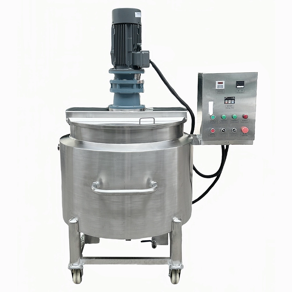
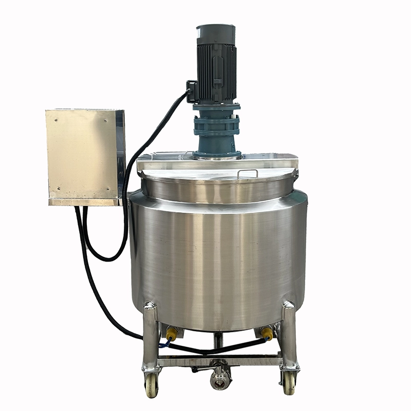
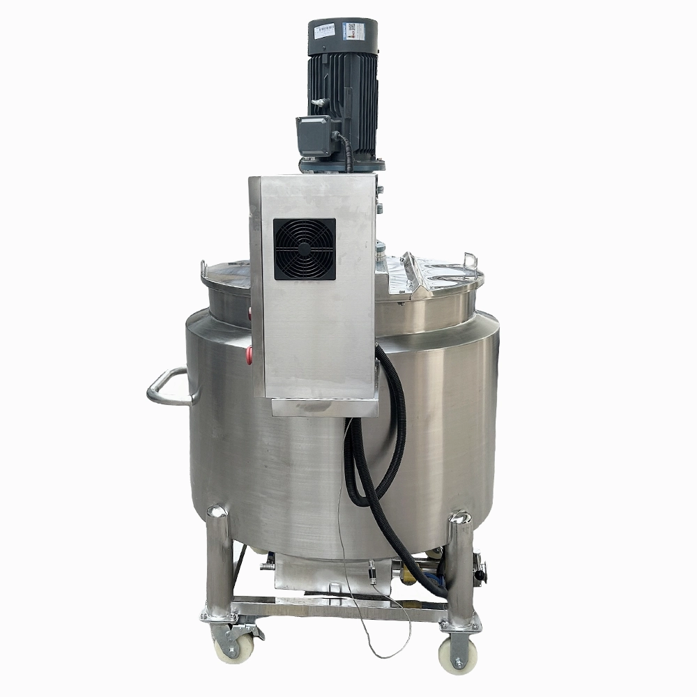
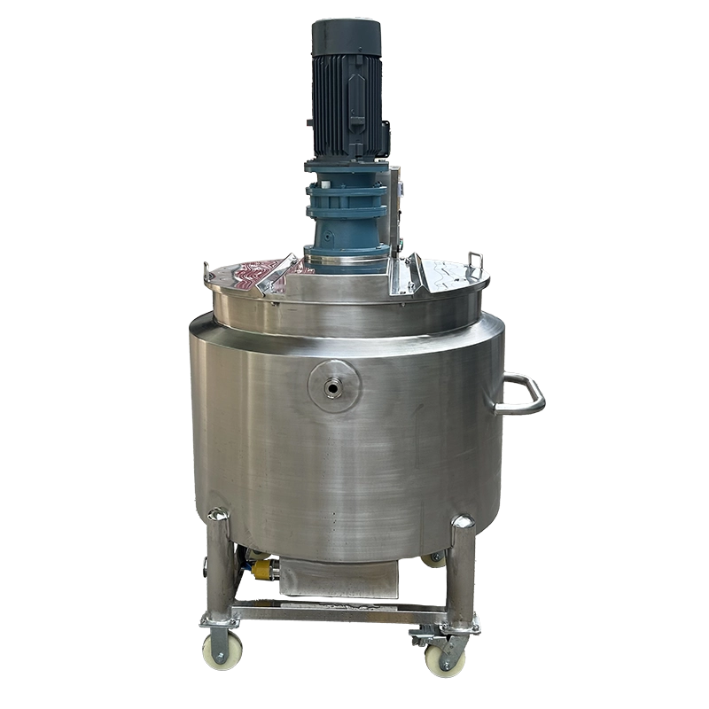
The 300L electric heating mixing tank combines single-direction frame agitation, PTFE wall scraping, and PLC/HMI control in an insulated, caster-mounted vessel. Designed for compatible cosmetic, personal-care, and food formulations, it provides atmospheric batch mixing without an assumed homogenizing function. Within the Stainless Steel Mixing Tanks range, this model emphasizes conventional agitation, thermal preparation, and an open-top operating arrangement.
| Tank Structure | Triple Layer (with Jacket & Insulation) | Types of Upper Heads | Flat Head / Open Top Design |
| Contact Material | SUS304 Stainless Steel | Cooling Method | Jacket Tap Water / Chiller Water Cooling |
| Outer Material | SUS304 Stainless Steel | Temperature Range | Water up to 98°C | Steam up to 120°C | Thermal Oil up to 200°C |
| Surface Finish | Inside Mirror Polished & Outside Brushed Finish | Discharge Type | Bottom Valve Discharge (Optional Air Pressure Assist) |
| Surface Roughness | Ra ≤ 0.4 μm (Sanitary Grade) | Discharge Valves | Butterfly Valve |
| Insulation Layer | With Insulation Layer | Connection Type | Tri-Clamp |
| Heating Jacket | Full Jacket / Coil Pipe Jacket (Optional) | mix_electrical_components | Schneider / Siemens / Omron (Optional/Customizable) |
| Full Capacity (L) | 360 | Voltage | Configurable to local grid (110V–480V, 50/60Hz, Single or 3-Phase) |
| Working Capacity (L) | 300 | Total Power (kW) | 21.5 |
| Main Mixing Type | Frame Mixer with Wall Scraper | Drive Type | Electric |
| Agitation Direction | Single Direction | Installation Type | Mobile (Caster-Mounted) |
| Mixing Speed (rpm) | 1-63 | Automation Level | Fully Automatic |
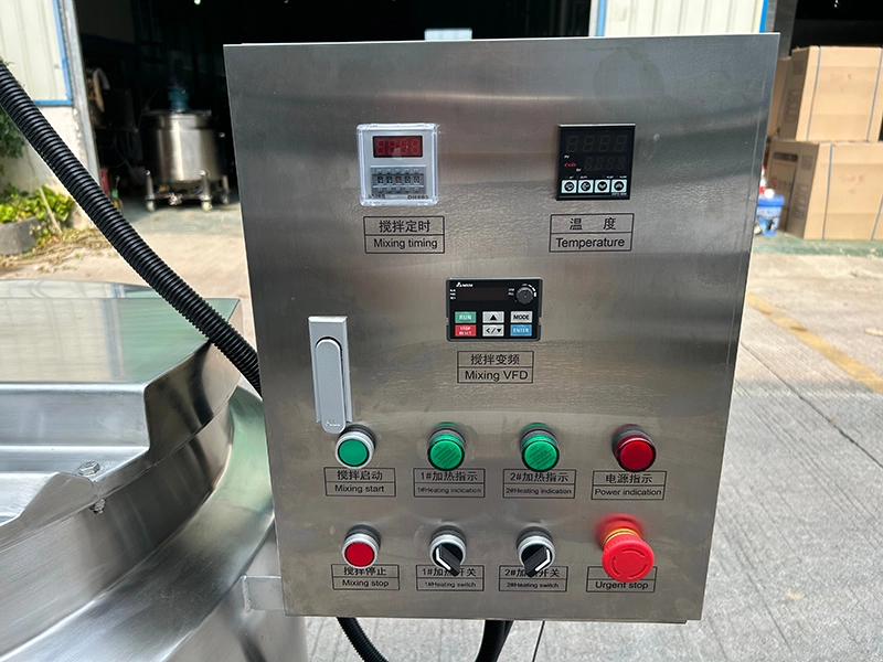
| Mixing Power (kW) | 3 | Control System | PLC + HMI Touch Screen Control |
| Frequency Converter | Variable Speed with VFD (Delta, Siemens, ABB, Schneider, Optional) | Machine Dimensions(L*W*H)mm | 1380*1090*1820 |
| Scraper System | High-Temperature PTFE Scraper | Machine Weight (kg) | 280 |
Product Gallery


Product Video
Product Overview
This tank provides 300L working capacity within a 360L vessel. Its role is batch blending and thermal preparation for compatible creams, lotions, shampoos, liquid soaps, and food formulations that can be processed using the supplied agitation arrangement.
The single-direction frame mixer provides bulk movement, while high-temperature PTFE scrapers sweep the vessel wall. Variable-frequency control allows agitation speed adjustment within the supplied range. These functions should be assessed against the actual material rather than treated as proof of suitability for every product in the application list.
This model differs from a tank with an integrated high-shear unit. No homogenizer is specified. Where a formulation requires both bulk agitation and bottom-entry rotor-stator processing, review Homogenizing Mixing Tanks instead.
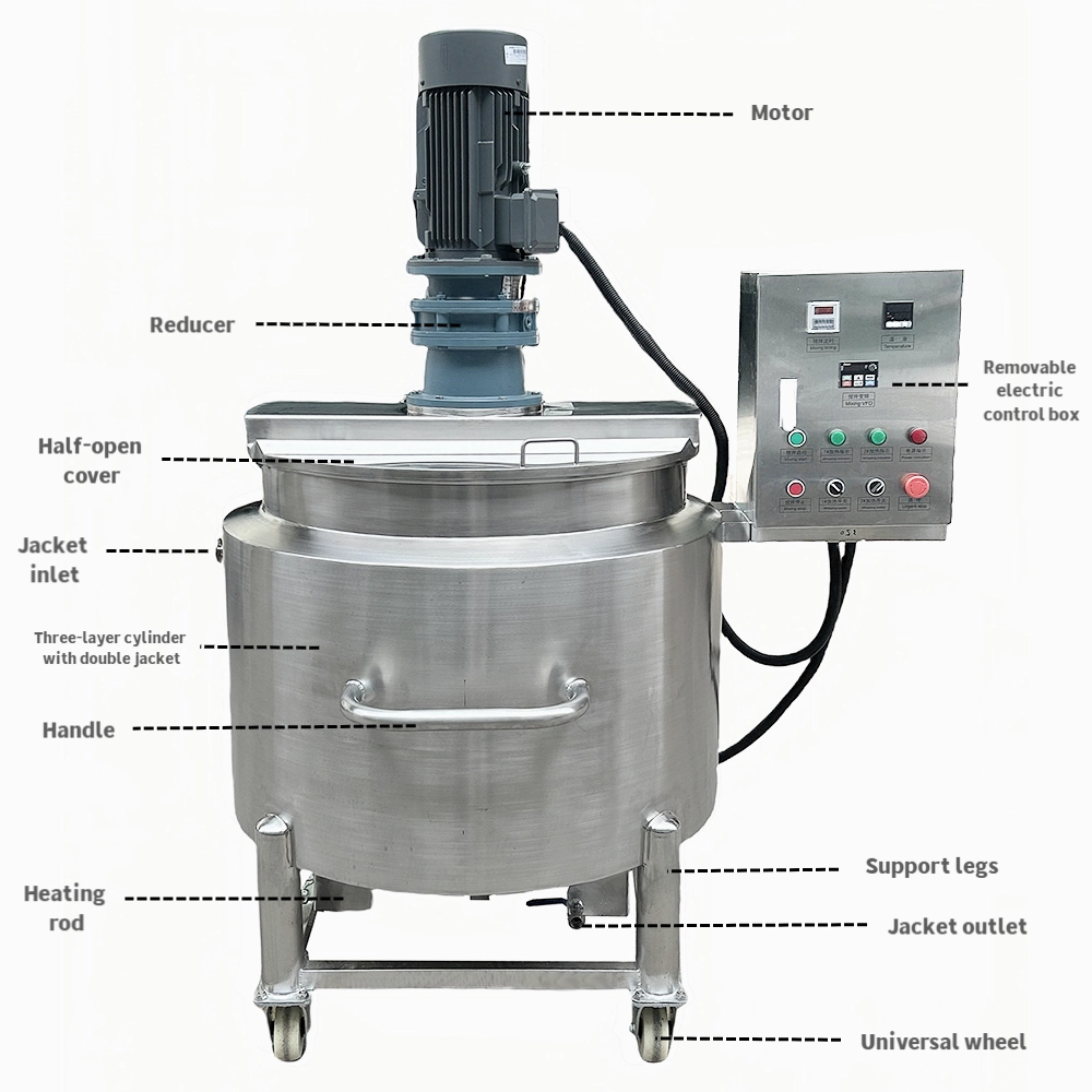
The electric-heating version uses jacketed, insulated construction, with jacket cooling available through an appropriate external supply. SUS304 is specified for both product-contact and outer construction.
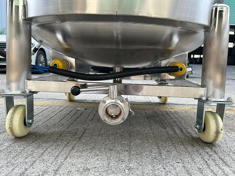
The open-top design supports the agreed charging and access method. A bottom butterfly valve and Tri-Clamp connections provide the specified product-handling interfaces. Caster mounting supports planned repositioning only under the approved handling conditions.
Machine Configuration
The triple-layer vessel incorporates a thermal jacket and insulation. Product-contact and outer construction are SUS304, with an internally mirror-polished surface and externally brushed finish. The supplied internal roughness specification is Ra ≤ 0.4 μm.
A 3 kW frame agitator operates in one direction with high-temperature PTFE wall scrapers. Variable-frequency control provides the specified 1–63 rpm agitation range. No high-shear homogenizer or vacuum system is established by the supplied data.
PLC and HMI touch-screen control provide the operating interface. The final order should identify the actual control functions, selected electrical components, drive, and motor brand.
The electric-heating arrangement and jacket cooling require the agreed utility systems. A bottom butterfly valve, Tri-Clamp connections, and caster-mounted structure complete the specified arrangement. Full-jacket or optional coil-pipe construction must be resolved in the technical agreement.
Key Features
- Single-direction frame agitation provides bulk mixing within the approved operating range.
- High-temperature PTFE scrapers sweep product along the internal vessel wall.
- Variable-frequency control allows agitation speed adjustment between 1 and 63 rpm.
- Electric jacket heating supports formulations requiring thermal preparation during mixing.
- Jacket cooling accommodates an approved tap-water or chilled-water supply.
- Insulated construction forms part of the specified three-layer vessel arrangement.
- PLC and HMI touch-screen control provide the supplied operating interface.
- Tri-Clamp connections support the specified removable product-path interfaces.
- Bottom butterfly valve provides the specified outlet for product discharge.
- Caster-mounted installation supports repositioning under approved handling conditions.
Applications
- Cosmetic Cream & Lotion, and Skin Care
- Detergents, Liquid Washing & Household Cleaning
- Juice, Beverage & Liquid Food
- Sauce, Condiment & Food Paste
Recommended Machines
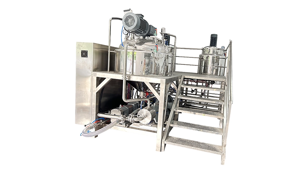
300L Vacuum Mayonnaise Emulsifying Machine with 3-Stage Inline Homogenizer & Oil Water Tanks for Salad Dressing, Ketchup & Sauce Processing
View Details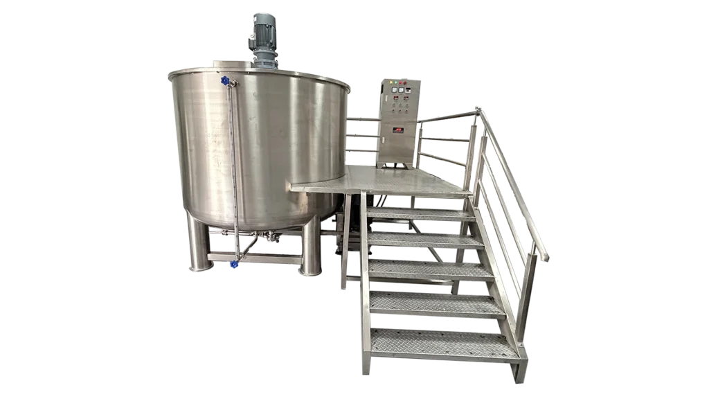
5000L Single Layer Homogenizer Mixing Tank for Liquid Soap, Detergent, Shampoo & Cosmetic Batch Production
View Details

Working Principle
Ingredients enter the vessel according to the approved formulation procedure. The initial charge, addition sequence, and batch quantity should allow the frame agitator and wall scrapers to engage the product effectively.
The agitator rotates in one direction to move the bulk material. PTFE scrapers sweep along the vessel wall, helping return wall-adjacent product to the moving batch. Agitation speed is selected within the supplied range according to the relevant processing stage.
Electric heating is applied through the selected jacket arrangement when required by the formulation. The specified control interface is used to operate the supplied functions, but the exact automatic sequence must be confirmed in the control-function schedule.
Where cooling is required, an approved external supply circulates through the jacket. Product-temperature measurement and acceptance conditions should be agreed separately from thermal-medium limits. The heating, mixing, and filling guide provides related context for temperature-sensitive handling.
After the required blending and thermal stages, product leaves through the bottom butterfly valve into the agreed receiving or transfer arrangement. This model provides conventional agitation rather than a confirmed high-shear or vacuum process. Formulations needing those additional functions require a different equipment assessment.
Optional Upgrades & Configurations
| Warranty | 24 Months | Payment Terms | 40% T/T Deposit, 60% Balance Before Shipment (Alibaba Trade Assurance Available) |
| Lead Time | 15–20 Working Days | Packaging | Standard Export Fumigation-Free Wooden Case |
Recommended Accessories


After-Sales & Technical Support
🔧 Common Problems
Potential symptoms include uneven ingredient distribution, material collecting along the wall, persistent bubbles, product temperature departing from the intended profile, unusual agitation noise, leakage at a Tri-Clamp connection, and slow or interrupted discharge. Operators may also observe scraper wear, inconsistent mixing at a smaller batch quantity, unexpected control messages, or movement from the approved operating position. These are inspection topics rather than documented faults of this particular machine. Record the process stage, batch quantity, formulation condition, and settings before selecting corrective action. A difference in finished-product condition should not automatically be attributed to insufficient agitator power. Charging order, ingredient condition, temperature, batch volume, and the operating method may also require review.
🛠 Troubleshooting
Problem: Ingredients remain unevenly distributed Possible Cause: Charging sequence, batch volume, material behavior, or agitation settings differ from the approved method Recommended Solution: Compare the batch record with the approved procedure and confirm effective agitator engagement before changing settingsProblem: Material accumulates along the wall Possible Cause: Scraper condition, installation, or product behavior requires review Recommended Solution: Isolate the equipment before inspecting the PTFE scraper arrangement against the supplied documentationProblem: Product temperature does not follow the intended profile Possible Cause: Heating settings, cooling conditions, measurement, or bulk circulation differs from the approved conditions Recommended Solution: Record the indicated temperature and process stage, then arrange qualified inspection of the relevant systemProblem: A Tri-Clamp connection leaks Possible Cause: The gasket, mating surfaces, alignment, or clamp condition requires inspection Recommended Solution: Isolate and drain the affected connection as instructed before inspecting it and replacing any confirmed defective componentProblem: The bottom outlet discharges slowly Possible Cause: Product flow behavior, discharge temperature, valve condition, or receiving arrangement is unsuitable Recommended Solution: Review the approved discharge method and inspect the isolated valve without applying unapproved pressureProblem: The HMI displays an unexpected alarm Possible Cause: A condition identified by the installed control program requires attention Recommended Solution: Record the alarm and follow the supplied instructions without bypassing protective functionsProblem: The tank shifts during operation Possible Cause: The approved positioning arrangement is not correctly established or needs inspection Recommended Solution: Stop operation and restore the supplier-approved restraint arrangement before restarting
🧼 Cleaning Method
1. Select the cleaning procedure approved for the formulation and contacted materials. 2. Discharge the remaining product through the agreed outlet arrangement. 3. Establish the temperature condition required for cleaning. 4. Isolate relevant energy sources according to the supplied instructions. 5. Remove accessible bulk residue using approved tools. 6. Perform the preliminary rinse specified for the product. 7. Apply the approved cleaning stage using its documented conditions. 8. Clean the frame agitator using the approved method. 9. Clean the PTFE scraper contact areas. 10. Clean the butterfly valve according to its supplied instructions. 11. Clean removable Tri-Clamp fittings where the procedure requires disassembly. 12. Inspect removed gaskets for residue or damage. 13. Complete the required final rinsing. 14. Perform sanitization only where required by the approved procedure. 15. Inspect product-contact surfaces for remaining residue. 16. Inspect cleaned components for damage. 17. Verify drainage. 18. Reassemble components according to the supplied instructions. 19. Release the equipment under the agreed cleanliness criteria.
📋 Maintenance
1. Isolate electrical energy according to the supplied maintenance procedure. 2. Isolate connected thermal services. 3. Confirm the required vessel temperature before access. 4. Inspect the frame agitator for visible damage. 5. Inspect agitator attachments according to the supplied procedure. 6. Inspect PTFE scraper elements for wear or deterioration. 7. Inspect the shaft and drive arrangement using the approved method. 8. Inspect the butterfly valve for leakage or damage. 9. Inspect Tri-Clamp gaskets for deterioration. 10. Inspect Tri-Clamp assemblies for damage. 11. Inspect the caster assemblies. 12. Inspect the operating-position restraint components. 13. Have qualified personnel inspect the motor and electrical equipment. 14. Have qualified personnel check PLC and HMI functions as instructed. 15. Service specified lubrication points using approved materials. 16. Complete the required functional checks after maintenance. 17. Record findings and corrective work before release to production.
⚙️ Installation
1. Verify the delivered tank against the approved configuration schedule. 2. Position the machine according to the installation drawing. 3. Establish the approved restraint arrangement for the caster-mounted tank. 4. Confirm charging clearance. 5. Confirm access to the control interface. 6. Confirm space for cleaning and component removal. 7. Confirm access to the bottom valve and receiving arrangement. 8. Have qualified personnel connect the electrical supply according to the delivered rating. 9. Connect the selected cooling supply. 10. Connect the approved cooling return or drainage arrangement. 11. Install the agreed discharge connection without imposing unsupported loads. 12. Verify Tri-Clamp assembly according to the supplied instructions. 13. Complete the prescribed protective-function checks. 14. Commission the heating function under the supplier’s procedure. 15. Commission the agitation function under the supplier’s procedure. 16. Verify the agreed PLC and HMI functions. 17. Trial representative material using the approved acceptance method. 18. Record the accepted operating setup. 19. Document permitted conditions for repositioning the tank.
🔩 Spare Parts
Why Choose This Machine
- Matches conventional mixing duties. The frame-and-scraper arrangement provides a defined option when the formulation does not require a separate high-shear processing stage.
- Provides a clear batch basis. The 300L working capacity supports planning without treating the 360L total vessel volume as routine usable capacity.
- Combines mixing and thermal preparation. Jacket heating and cooling can be incorporated into the approved batch method, subject to the selected configuration and utility duty.
- Provides a central operating interface. PLC/HMI control brings the supplied functions into an identified control arrangement without assuming unconfirmed software capabilities.
- Supports removable connections. The specified Tri-Clamp arrangement can be reviewed for discharge and cleaning access. The clamp versus flange connection guide provides supporting context.
- Allows planned repositioning. Caster mounting offers layout flexibility where the approved load, temperature, isolation, and handling conditions permit movement.
Batch time, cleaning-time savings, product uniformity, and labor reduction require application-specific evidence rather than being guaranteed from these features alone.
Frequently Asked Questions
Installation Requirements
The listed empty weight is 280 kg. Floor and handling assessments must include product, accessories, connected equipment, and applicable operating loads. Establish the approved restraint method for the caster-mounted tank before operation.
Confirm the destination electrical supply against the delivered rating. The listed total power is 21.5 kW, but wiring, protection, and isolation must follow the final electrical documentation. Do not infer heater power by subtracting the mixing motor rating.
Provide the selected cooling supply and its return or drainage arrangement. Confirm any additional utility requirements from the final configuration; compressed-air consumption has not been supplied.
Arrange the bottom outlet and Tri-Clamp connections without imposing unsupported loads. Confirm the suitability of the equipment for the ingredients and installation environment; no hazardous-area rating has been established.
Related Articles
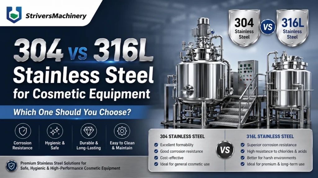


Technical Buyer's Handbook & Deep Insight
Ready to Get a Quote?
Contact our team directly for pricing, customization options, and delivery timelines.
💬 WhatsApp Us NowGet Your Download Link
Please fill in your details and we'll send the download link to your email.