
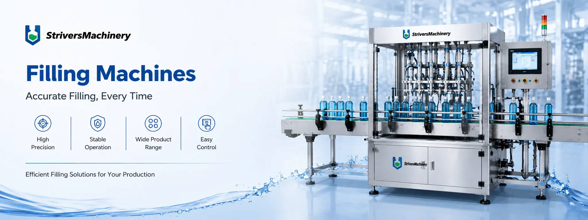
6-Head Automatic Gear Pump Filler for Cosmetic CREAM&Liquids | High-Viscosity Lotion & Shampoo Filling Machine
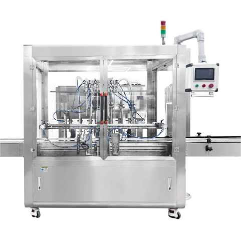
The 6-Head Servo Gear Pump Filling Machine fills compatible cosmetic liquids, lotions, creams, and shampoos into bottles and jars. Servo-driven nozzle lifting supports filling inside the container, while a shared hopper and automatic replenishment pump maintain product supply. The included conveyor handles containers through the filling sequence, with manual loading or compatible upstream bottle-feeding equipment. Capping is a separate operation.
| Filling Principle | Gear Pump | Material Contact Parts | SUS316L Stainless Steel (Pharmaceutical Grade) |
| Machine Layout Type | Inline / Linear Filling Machine | Machine Frame Material | SUS304 Stainless Steel Frame |
| fill_automation_level | Fully Automatic (Inline Integration) | Conveyor System | Conveyor Optional (POM Slat Chain, SUS304 Chain, PVC/PU Flat Belt) |
| Container Type | Bottles & Jars | Motor Brand | Top-Tier Chinese Servo (Inovance / Equivalent) |
| Container Material | PET/HDPE/PP / Glass | Servo Drive Type | Servo-driven Filling Pump Motor / Servo-driven Filling Head with Lift-up / Servo-driven Conveyor Belt Motor |
| Product Viscosity | Low Viscosity (Water, Toner, Alcohol) / Medium Viscosity (Lotion, Shampoo, Oil) / High Viscosity (Cream, Paste, Mascara) | Servo Motor Brand | Other / Customer Specified |
| Filling Volume Range (ml) | 5-5000 | Photoelectric Brand | SICK |
| Filling Accuracy | ±0.5% | Pneumatic Components Brand | AirTAC |
| Filling Head/Heads | 6 | Cylinder Brand | Airtac |
| Filling Nozzle Movement | Fixed Type | fill_electrical_components | Schneider / Siemens / Omron (Optional/Customizable) |
| Nozzle Type | Pneumatic Shut-off Nozzles (Anti-Drip) | Voltage | Configurable to local grid (110V–480V, 50/60Hz, Single or 3-Phase) |
| Drip Prevention | Pneumatic Anti-Drip Mechanism Included | Total Power (kW) | 3 |
| Production Speed (Bottles Per Minute) | 50 | Drive Type | Electro-Pneumatic Combined |
| Production Capacity (Bottles Per Hour) | 3000 | Installation Type | Mobile (Caster Wheels) |
| With Hopper | Yes | Automation Level | Fully Automatic |
| Hopper Volume (L) | 200 | Control System | PLC + HMI Touch Screen Control |
| Bottle Handling Method | Manual | PLC System | Mitsubishi |
| fill_installation_type | Floor-standing | Control & Interaction Systems | Fully Automated (High-Tech / Industry 4.0) |
| With Machine Cover | Yes | Machine Dimensions(L*W*H)mm | 2000mm × 810mm × 2200mm |
| Capping Type | Filling Only (Without Capping), Capping Machine Sold Separately | Machine Weight (kg) | 600 |
Product Video
Product Overview
StriversMachinery’s six-head gear-pump filler combines linear container handling with vertically moving filling nozzles. It serves manufacturers packaging compatible water-like liquids, lotions, shampoos, and creams that require an automatic filling stage within a bottle or jar production line.
The filling assembly lowers the nozzles into the containers and raises them during the operating sequence. This is a vertical lifting arrangement: the nozzles do not travel horizontally with continuously moving bottles. Container presentation and nozzle movement are coordinated at the filling positions.
A shared product hopper supplies the dosing system. The standard feed pump replenishes it automatically according to the material level. The hopper provides storage and supply without integrated heating or agitation, so the formulation must remain suitable for filling under the selected upstream preparation and holding conditions.
The included conveyor accepts manually supplied containers or can be connected to compatible bottle-feeding equipment. Finished containers leave the filling stage for separate closing and subsequent packaging.
Selection should consider actual formulation behavior, container geometry, target dose, and production requirements. Particle-containing, strongly abrasive, or exceptionally demanding formulations require a separate assessment rather than being treated as standard applications.
Machine Configuration
The machine combines six filling outlets, servo-controlled gear-pump dosing, and a servo lifting assembly that positions the nozzles vertically inside compatible containers. Pneumatic shut-off nozzles control product release at the outlets.
A shared 200 L hopper supplies the filling system. The included replenishment pump starts and stops according to material level, while the hopper itself provides storage without heating or mixing. The conveyor is included and coordinates container transfer through the filling stage.
Mitsubishi PLC and Inovance touchscreen controls provide the operating interface. SICK photoelectric components and AirTAC pneumatic components form part of the configuration. Other electrical and servo selections follow the agreed order.
The enclosed, floor-standing machine uses a SUS304 stainless steel frame and specified SUS316L stainless steel product-contact metal components. Flexible connections and seals require separate compatibility selection. Capping equipment is not included.
Key Features
- Six filling outlets process compatible bottles or jars within a coordinated linear sequence.
- Servo nozzle lifting supports vertical entry into containers during the filling operation.
- The filling assembly moves vertically without horizontally following continuously moving bottles.
- Pneumatic shut-off nozzles help control residual product release after dosing.
- A shared hopper supplies the filling system from one product buffer.
- The included feed pump replenishes the hopper automatically according to material level.
- The standard conveyor supports manual container loading or compatible upstream bottle-feeding equipment.
- Mitsubishi PLC and Inovance touchscreen controls centralize routine operation.
- The enclosed arrangement groups dosing, nozzle movement, and container handling within one machine.
Applications
- Cosmetic Cream & Lotion, and Skin Care
- Detergents, Liquid Washing & Household Cleaning
- Pharmaceutical & Ointment Products
- Toothpaste & Oral Care Products
Recommended Machines



Working Principle
The six-head automatic filler coordinates container positioning, gear-pump dosing, and vertical nozzle movement. An automatic replenishment arrangement supplies the shared hopper so the filling system can draw product during operation.
- Product replenishment: The feed pump transfers product from the upstream source into the shared hopper. Material-level control starts and stops replenishment according to the supply condition.
- Container infeed: Empty bottles or jars enter on the included conveyor. Operators can load them manually, or compatible upstream equipment can provide the container supply.
- Filling presentation: The handling arrangement presents containers beneath the six filling outlets for the dosing sequence.
- Nozzle lowering: The servo lifting assembly lowers the nozzles into compatible container openings to the selected operating position.
- Gear-pump dosing: Controlled pump operation delivers product through the filling pathways. Pneumatic shut-off nozzles govern release at the outlets, while the lifting assembly carries out its configured vertical movement.
- Nozzle clearance: After delivery, the nozzles close and rise clear of the containers under the coordinated sequence.
- Container discharge: Filled containers continue along the conveyor toward collection or separately supplied closing equipment.
The nozzles do not follow bottles horizontally during filling. Product preparation, source replenishment, downstream capping, and required quality checks remain part of the wider production arrangement.
Optional Upgrades & Configurations
Custom Requirements
Corrosive-Resistant Construction for Strong Acids & Alkalis
Explosion-Proof Filling Systems for Flammable & Hazardous Environments
Custom Machine Layouts & Space-Saving Footprint Constraints
Extended & Custom-Length Long-Distance Conveyor Systems
Designated electrical component brands (Siemens PLC, Festo Pneumatics, etc.)
Irregular Bottle Shapes & Custom Packaging Solutions
Suitable Products
| Warranty | 24 Months | Payment Terms | 40% T/T Deposit, 60% Balance Before Shipment (Alibaba Trade Assurance Available) |
| Lead Time | 15–20 Working Days | Packaging | Standard Export Fumigation-Free Wooden Case |
After-Sales & Technical Support
🔧 Common Problems
Possible operating symptoms include uneven container presentation, hesitation on the conveyor, or inconsistent clearance during nozzle entry and withdrawal. Filled quantities may differ between outlets or vary during a production run. Foaming, visible bubbles, wet container rims, or product strings may appear during filling. Hopper level may fluctuate, replenishment may become irregular, or product movement toward the filling system may be interrupted. Other symptoms include abnormal pump noise, inconsistent pneumatic shut-off action, unusual lifting movement, product leakage at accessible connections, or accumulation of filled containers at the discharge. Product appearance or flow may also change during holding in the unheated, non-agitated hopper.
🛠 Troubleshooting
Problem: Filled quantities differ between outlets. Possible Cause: Unequal product presentation, air in a pathway, or an unsuitable dosing setup. Recommended Solution: Measure results by outlet and inspect accessible product paths before reviewing adjustments.Problem: Foam or wet rims appear during filling. Possible Cause: Unsuitable nozzle position, delivery conditions, or formulation behavior. Recommended Solution: Assess the complete filling cycle with representative product before changing nozzle movement or dosing settings.Problem: Nozzles approach containers incorrectly. Possible Cause: Misaligned guides, an incorrect format setup, or containers differing from approved samples. Recommended Solution: Stop operation and inspect presentation and clearance before reviewing the lift setup.Problem: Hopper replenishment becomes irregular. Possible Cause: An interrupted upstream supply, restricted transfer, or a level-control issue. Recommended Solution: Inspect the source and transfer route before qualified checking of the replenishment controls.Problem: Shut-off action becomes inconsistent. Possible Cause: Residue, unstable air supply, or component wear. Recommended Solution: Inspect the outlet and air supply against the specified 0.4–0.6 MPa range before assessing replacement.Problem: Filled containers accumulate at discharge. Possible Cause: Restricted collection or downstream equipment unable to accept the flow. Recommended Solution: Review the discharge route and downstream operation before increasing the filling rate.
🧼 Cleaning Method
1. Stop the filling machine according to the operating procedure. 2. Stop upstream product replenishment under the prescribed sequence. 3. Remove remaining containers from the conveyor. 4. Recover residual hopper product using the approved handling method. 5. Isolate the electrical supply under the maintenance instructions. 6. Isolate the compressed-air supply according to the equipment procedure. 7. Secure the nozzle-lifting assembly according to the service instructions. 8. Relieve retained pressure before accessing affected components. 9. Remove accessible product-contact parts under the equipment instructions. 10. Clean the hopper using a product-compatible approved method. 11. Clean the replenishment pathway according to the installed pump instructions. 12. Clean the dosing pathways according to the filling-system instructions. 13. Clean accessible nozzle components according to their service procedures. 14. Rinse reusable contact parts where required by the cleaning method. 15. Inspect cleaned areas for retained product or cleaning residues. 16. Dry reusable components using the established production procedure. 17. Reassemble removed parts according to the equipment instructions. 18. Record cleaning completion according to the facility’s requirements.
📋 Maintenance
1. Inspect accessible product pathways for leakage or deterioration. 2. Examine replenishment connections for loosening or damage. 3. Check hopper level-control components under the prescribed maintenance procedure. 4. Inspect filling nozzles for residue or irregular shut-off movement. 5. Examine the nozzle-lifting assembly for obstruction or abnormal travel. 6. Check accessible nozzle supports and attachments for loosening. 7. Inspect container guides for wear affecting presentation. 8. Check conveyor tracking and accessible wear components. 9. Examine pneumatic tubing and fittings for leakage or abrasion. 10. Inspect photoelectric sensing surfaces for contamination or displacement. 11. Check enclosure panels and accessible protective components for damage. 12. Examine frame fasteners and the installed securing arrangement. 13. Keep motor and drive ventilation areas clear. 14. Review electrical connections through qualified maintenance personnel. 15. Apply lubrication only where specified in the installed component instructions. 16. Verify filling and nozzle-motion performance after relevant maintenance. 17. Record inspections, adjustments, and replaced components in the maintenance log.
⚙️ Installation
1. Position the machine on a firm, level floor. 2. Establish access for container supply, product replenishment, and servicing. 3. Verify clearance for nozzle movement against the final arrangement drawing. 4. Secure the mobile frame using the prescribed installation arrangement. 5. Connect protective earthing through qualified electrical personnel. 6. Connect the electrical supply specified for the ordered configuration. 7. Connect compressed air within the required 0.4–0.6 MPa range. 8. Position the upstream product source for the approved replenishment route. 9. Assemble product connections according to the equipment instructions. 10. Set conveyor guides for the approved container. 11. Align filling outlets with the presented openings. 12. Check nozzle clearance under the commissioning procedure. 13. Introduce representative product using the approved handling method. 14. Verify level-controlled hopper replenishment. 15. Adjust the dosing setup for the target volume. 16. Check filled quantity separately at each outlet. 17. Assess product appearance during the full filling cycle. 18. Verify filled-container transfer to collection or separate downstream equipment. 19. Document the accepted setup before routine production.
🔩 Spare Parts
Why Choose This Machine
- Coordinated multi-container filling: Six outlets provide a production arrangement for manufacturers moving beyond single-head filling, subject to the required formulation and package assessment.
- Adjustable vertical nozzle positioning: Servo lifting allows the filling position to be reviewed against container depth and product behavior rather than relying on a fixed-height outlet.
- Automatic product replenishment: Level-controlled feeding reduces the need for repeated manual charging of the hopper during a sustained run.
- Shared product buffer: One hopper supplies the filling system, bringing the material-supply arrangement into a defined part of the machine configuration.
- Flexible container supply: The included conveyor supports manual loading and allows compatible upstream feeding equipment to be considered as production requirements develop.
- Separate closing selection: Filling-only supply allows the capper to be chosen against the actual bottle, jar, and closure format.
- Centralized supervision: PLC and touchscreen controls bring routine operation to one interface while operators manage upstream materials, checks, and downstream handling.
Frequently Asked Questions
Installation Requirements
Allow overhead and working clearance for the servo nozzle-lifting assembly. The listed overall height does not independently establish the maximum operating or maintenance envelope.
Provide an electrical supply matched to the ordered voltage, frequency, and phase configuration. The supplied total-power figure is 3 kW. Qualified personnel should complete protective earthing and electrical connection according to the final equipment documentation.
Provide compressed air at 0.4–0.6 MPa with quality appropriate to the installed pneumatic components. Route utility lines clear of the conveyor and moving filling assembly.
Position the upstream product source to suit the replenishment pump and transfer route. Establish a separate plan for downstream capping and collection. The hopper has no heating or agitation, so upstream preparation and holding conditions must maintain product suitability.
Related Articles


Technical Buyer's Handbook & Deep Insight
Ready to Get a Quote?
Contact our team directly for pricing, customization options, and delivery timelines.
💬 WhatsApp Us NowGet Your Download Link
Please fill in your details and we'll send the download link to your email.