
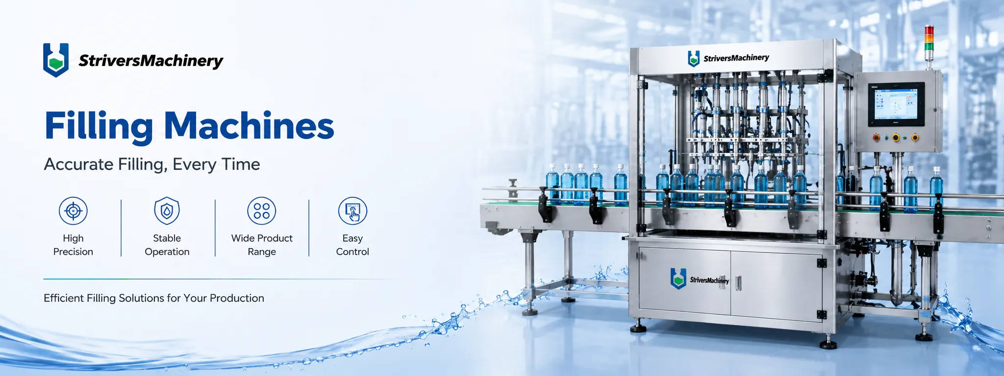
Automatic Single Head Servo Driven Gear Pump Liquid Filler with Auto Feeding System for Viscous Oil, Honey, Cream & Shampoo

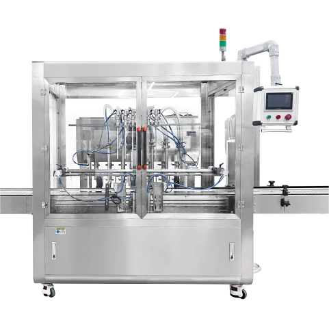
The Single-Head Servo Gear Pump Filler combines automatic product replenishment with conveyor-based filling for compatible liquids, lotions and creams. An integrated piston feed pump replenishes the 30 L hopper, while the servo-driven gear pump controls dispensing through a pneumatic shut-off nozzle. Bottles can be placed manually on the conveyor or supplied through a connected bottle unscrambler, making this a flexible option within the liquid filling machines range.
| Integrated Functions | Automatic Filling | Motor Brand | Top-Tier Chinese Servo (Inovance / Equivalent) |
| Filling Principle | Gear Pump | Servo Drive Type | Servo-driven Filling Pump Motor / Servo-driven Conveyor Belt Motor |
| Machine Layout Type | Inline / Linear Filling Machine | Servo Motor Brand | Inovance/XINJE/Leadshine |
| Container Type | Bottles & Jars | Photoelectric Brand | Panasonic |
| Container Material | PET/HDPE/PP / Glass | Pneumatic Components Brand | AirTAC |
| Product Viscosity | Low Viscosity (Water, Toner, Alcohol) / Medium Viscosity (Lotion, Shampoo, Oil) / High Viscosity (Cream, Paste, Mascara) | Voltage | Configurable to local grid (110V–480V, 50/60Hz, Single or 3-Phase) |
| Filling Volume Range (ml) | 5-5000ml | Total Power (kW) | 2 |
| Filling Accuracy | ±0.5% | Air Pressure | 0.4–0.8 MPa |
| Filling Head/Heads | 1 | Drive Type | Electro-Pneumatic Combined |
| Nozzle Type | Pneumatic Shut-off Nozzles (Anti-Drip) | Installation Type | Mobile (Caster-Mounted) |
| Drip Prevention | Pneumatic Anti-Drip Mechanism Included | Automation Level | Fully Automatic |
| Production Speed (Bottles Per Minute) | 25-40 | Electrical Components | Top-tier Chinese Brand: DELIXI / CHINT / People Electric / TENGEN |
| With Hopper | Yes | Control System | PLC + HMI Touch Screen Control |
| Hopper Volume (L) | 30 | PLC System | INOVANCE/Xinje or equivalent brand |
| Feeding Method | Integrated Piston Pump | HMI / Touch Screen | Kinco/MCGS/INOVANCE/Xinje/Flexem or equivalent brand |
| Material Contact Parts | SUS316L Stainless Steel (Pharmaceutical Grade) | Machine Dimensions(L*W*H)mm | 2000*760*1500 |
| Machine Frame Material | SUS304 Stainless Steel Frame / Aluminum Alloy | Machine Weight (kg) | 200 |
| Conveyor System | Conveyor Optional (POM Slat Chain, SUS304 Chain, PVC/PU Flat Belt) | ||
Product Overview
This single-head inline filler separates product replenishment from the dispensing operation. The feed pump supplies the hopper automatically, reducing repeated manual top-ups, while the servo-driven gear pump handles the filling quantity.
The filling range is 5–5000 mL. Suitable products include many water-like liquids, lotions and creams, including viscous oils, honey and shampoo. The formulation’s flow behavior, temperature and compatibility with the wetted pathway determine the operating setup.
The 30 L hopper provides a local product supply for the filling system. Heating and agitation are available as options where the product needs temperature control or movement during holding.
A conveyor carries bottles through the filling station. Operators can load empty containers onto the conveyor, or a bottle unscrambler can be connected for automatic infeed. Panasonic photoelectric components support the supplied sensing functions, while PLC and HMI controls coordinate the operating sequence.
The rated production speed is 25–40 bottles per minute. Actual output varies with quantity, product behavior and packaging conditions. Capping, sealing and labeling are separate operations that can be arranged around the filled container.
Machine Configuration
The product-supply section includes an integrated piston feed pump and a 30 L hopper. Automatic start-stop replenishment supplies the hopper as required, keeping the feeding duty separate from the gear-pump dispensing function.
A servo-driven gear pump delivers product to one filling nozzle. The pneumatic shut-off mechanism controls the end of dispensing. Conveyor transport and bottle positioning bring containers through the inline filling station.
PLC and HMI controls coordinate the supplied functions. Panasonic photoelectric components and AirTAC pneumatic components support sensing and actuation. Servo, PLC, HMI and electrical brands follow the selected project configuration.
The frame combines SUS304 stainless steel and aluminum alloy, with SUS316L stainless steel wetted components in the product pathway. Hopper heating and agitation are optional. The conveyor construction and any connected bottle unscrambler are selected around the packaging format and factory layout.
Key Features
- Automatic start-stop replenishment reduces repeated manual filling of the hopper.
- Separate feeding and dispensing pumps perform distinct product-handling duties.
- A 30 L hopper provides a local buffer for the filling circuit.
- Servo-driven gear-pump dispensing supports adjustable filling quantities.
- A pneumatic shut-off nozzle controls product cut-off after dispensing.
- Conveyor transport supports manual bottle loading or connected automatic infeed.
- Optional hopper heating and agitation address formulation-specific holding requirements.
- PLC and HMI controls bring the supplied operating functions together.
Applications
- Cosmetic Cream & Lotion, and Skin Care
- Hair Care, Personal Care & Body Wash
- Pharmaceutical & Ointment Products
Recommended Machines
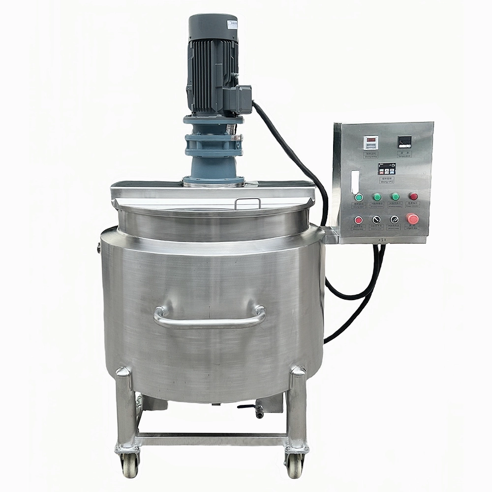
300L Open-Top Stainless Steel Electric Heating Jacketed Mixing Tank with Agitator for Cosmetic Cream, Lotion, Shampoo, Liquid Soap and Food Processing
View Details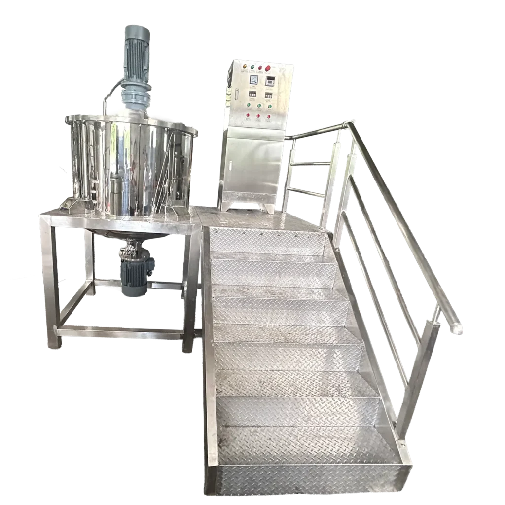
500L Semi-Open Liquid Soap & Shampoo Making Machine with Bottom Water-Cooled Homogenizer & Operation Platform
View Details
Working Principle
Prepared product is connected to the machine’s feed arrangement. The integrated piston feed pump replenishes the 30 L hopper through automatic start-stop operation, providing a local supply for dispensing.
Empty bottles enter the conveyor through manual loading or a connected bottle unscrambler. The supplied handling system presents each container at the filling position.
The servo-driven gear pump draws product from the hopper and delivers it through the single filling nozzle. Pump settings are established for the target quantity and the actual formulation.
At the end of the fill, the pneumatic shut-off nozzle closes to control trailing product. The bottle then moves onward, making the filling position available for the next container.
When optional hopper heating or agitation is supplied, those functions maintain the product conditions defined for the packaging task. Their settings follow the formulation rather than a general requirement applied to every liquid or cream.
The PLC and HMI coordinate the supplied feeding, dispensing and bottle-handling functions. Routine operation includes checking the product supply, filled quantity and condition of the package opening.
Filled bottles proceed to collection or separate closure equipment. Format or formulation changes require the corresponding setup and filling checks before production resumes.
Optional Upgrades & Configurations
Custom Requirements
Corrosive-Resistant Construction for Strong Acids & Alkalis
Explosion-Proof Filling Systems for Flammable & Hazardous Environments
Custom Machine Layouts & Space-Saving Footprint Constraints
Extended & Custom-Length Long-Distance Conveyor Systems
Designated electrical component brands (Siemens PLC, Festo Pneumatics, etc.)
Irregular Bottle Shapes & Custom Packaging Solutions
Suitable Products
| Warranty | 24 Months | Payment Terms | 40% T/T Deposit, 60% Balance Before Shipment (Alibaba Trade Assurance Available) |
| Lead Time | 15–20 Working Days | Packaging | Standard Export Fumigation-Free Wooden Case |
After-Sales & Technical Support
🔧 Common Problems
Possible operating symptoms include variation in filled quantity, intermittent product flow, visible air in the product tubing or product trailing after nozzle closure. The hopper may replenish irregularly, remain below the intended operating level or show an unexpected change in product condition. Bottles may stop out of position, move unevenly through the filling section or show residue around the opening. Operators may also observe interrupted automatic infeed, repeated HMI messages, audible pneumatic leakage or inconsistent response from the nozzle. With optional heating or agitation, temperature readings or visible product movement may differ from the intended operating condition. During changeover, residue, color or fragrance may remain in the feed pump, hopper or dispensing pathway. Record the formulation, quantity, packaging format and affected operating stage when investigating a symptom.
🛠 Troubleshooting
Problem: Filled quantity varies during production. Possible Cause: Entrained air, product-supply changes or dosing conditions affect dispensing. Recommended Solution: Review the supply condition and compare measured fills before changing settings.Problem: Automatic replenishment becomes irregular. Possible Cause: The source supply, feed pathway or start-stop control condition is interrupted. Recommended Solution: Review the operating message and product availability. Isolate the equipment before inspecting the feed circuit.Problem: Product trails after filling. Possible Cause: Deposits, seal wear or pneumatic shut-off operation affects the nozzle. Recommended Solution: Stop and isolate the machine before inspecting and cleaning the affected assembly.Problem: Bottles stop in the wrong position. Possible Cause: Guide settings, container presentation or sensing conditions differ from the approved setup. Recommended Solution: Check the format arrangement and accessible sensor surfaces before restarting.Problem: Automatic bottle infeed is interrupted. Possible Cause: A bottle obstruction or an unsuitable unscrambler setup affects presentation. Recommended Solution: Stop the connected equipment and follow its approved access procedure.Problem: Product condition changes in the hopper. Possible Cause: Holding conditions or selected heating and agitation settings do not suit the formulation. Recommended Solution: Review the formulation requirements and actual product conditions before adjusting the setup.Problem: The machine repeatedly pauses. Possible Cause: A required operating condition or permission is absent. Recommended Solution: Read the HMI message and correct the identified condition without bypassing protections.
🧼 Cleaning Method
1. Stop production through the approved shutdown sequence. 2. Remove containers from the designated working positions. 3. Recover remaining product through the approved discharge route. 4. Bring heated components to the safe access condition where heating is fitted. 5. Isolate electrical and pneumatic energy before manual access. 6. Release retained pressure through the designated procedure. 7. Disconnect the external product supply where required. 8. Drain the hopper through its approved emptying arrangement. 9. Remove designated detachable nozzle and connection components. 10. Pre-rinse the feed pathway with a formulation-compatible medium. 11. Clean the piston feed pump according to its component instructions. 12. Clean the hopper through the approved access method. 13. Clean optional agitation components where fitted. 14. Clean the gear-pump dispensing circuit according to its instructions. 15. Clean detachable nozzle parts through their permitted method. 16. Rinse until the specified cleaning-agent acceptance criteria are satisfied. 17. Inspect accessible components for retained residue. 18. Reassemble removed parts using the specified connection method. 19. Perform post-cleaning checks before returning to production.
📋 Maintenance
1. Establish the service schedule from the installed component documentation. 2. Isolate electrical and pneumatic energy before accessing service assemblies. 3. Release retained pressure through the approved procedure. 4. Inspect source-feed connections for leakage or deterioration. 5. Examine piston feed-pump components during approved service access. 6. Check the automatic replenishment function through the designated test method. 7. Inspect the hopper and outlet connections for visible damage. 8. Examine gear-pump wetted components according to their service instructions. 9. Check pneumatic shut-off nozzle seals for wear or deposits. 10. Inspect product tubing for chemical attack or deterioration. 11. Examine conveyor guides and accessible attachments for looseness. 12. Clean Panasonic photoelectric sensing surfaces using the permitted procedure. 13. Inspect AirTAC pneumatic tubing and fittings for damage. 14. Service installed cylinders according to their identified instructions. 15. Inspect optional heating components through the approved service method. 16. Maintain optional agitation components according to their documentation. 17. Arrange qualified inspection of electrical terminals and protective devices. 18. Test supplied stop functions through the approved functional method. 19. Inspect caster restraints before returning the machine to operation. 20. Record service findings against the affected circuit or component.
⚙️ Installation
1. Review the approved layout and container-format drawings. 2. Verify the delivery route against the final transport envelope. 3. Obtain approval of the floor for the complete operating load. 4. Inspect delivered assemblies for visible transport damage. 5. Position the equipment using the designated handling method. 6. Secure the caster-mounted base at its operating location. 7. Position the external product source according to the feed-pump instructions. 8. Connect the feed pathway using the specified compatible components. 9. Install the selected conveyor arrangement according to its drawings. 10. Connect the bottle unscrambler where included in the configuration. 11. Arrange electrical connection by qualified personnel using the final wiring schedule. 12. Verify protective earthing before electrical commissioning. 13. Connect the regulated compressed-air supply according to the pneumatic schedule. 14. Perform the specified pre-use cleaning procedure. 15. Prepare the bottle guides and filling position for the selected container. 16. Verify the supplied detection and stop functions. 17. Commission automatic replenishment through the approved sequence. 18. Commission optional hopper heating and agitation where fitted. 19. Set the target filling quantity through the control interface. 20. Evaluate representative product and containers against the acceptance criteria. 21. Document the approved setup before routine production.
🔩 Spare Parts
Why Choose This Machine
Prepared product is connected to the machine’s feed arrangement. The integrated piston feed pump replenishes the 30 L hopper through automatic start-stop operation, providing a local supply for dispensing.
Empty bottles enter the conveyor through manual loading or a connected bottle unscrambler. The supplied handling system presents each container at the filling position.
The servo-driven gear pump draws product from the hopper and delivers it through the single filling nozzle. Pump settings are established for the target quantity and the actual formulation.
At the end of the fill, the pneumatic shut-off nozzle closes to control trailing product. The bottle then moves onward, making the filling position available for the next container.
When optional hopper heating or agitation is supplied, those functions maintain the product conditions defined for the packaging task. Their settings follow the formulation rather than a general requirement applied to every liquid or cream.
The PLC and HMI coordinate the supplied feeding, dispensing and bottle-handling functions. Routine operation includes checking the product supply, filled quantity and condition of the package opening.
Filled bottles proceed to collection or separate closure equipment. Format or formulation changes require the corresponding setup and filling checks before production resumes.
Frequently Asked Questions
Installation Requirements
Assess floor loading for the operating arrangement, including product in the 30 L hopper. Secure the caster-mounted base at the designated operating position.
Prepare the electrical supply for the ordered voltage, frequency and phase configuration. The listed machine power is 2 kW. Use the final load schedule for the selected heating, agitation and auxiliary-equipment configuration.
Provide regulated compressed air within the specified 0.4–0.8 MPa range. Air consumption and treatment requirements follow the final pneumatic schedule.
Position the external product supply according to the feed-pump installation instructions. Support hoses and connections so they remain accessible for inspection, cleaning and safe disconnection.
For automatic bottle infeed, allocate space for the selected unscrambler and its connection to the conveyor. Coordinate discharge with the receiving closure or collection arrangement.
Provide suitable cleaning-liquid collection and waste handling. For flammable or otherwise sensitive formulations, assess the complete equipment configuration and installation environment before operation.
Related Articles


Technical Buyer's Handbook & Deep Insight
Ready to Get a Quote?
Contact our team directly for pricing, customization options, and delivery timelines.
💬 WhatsApp Us NowGet Your Download Link
Please fill in your details and we'll send the download link to your email.