

7.5kW Hydraulic Lifting High Speed Disperser Machine for Paint, Coating, Ink & Chemical Liquid Mixing

The 7.5kW Hydraulic Lifting High Speed Disperser is a floor-mounted batch mixer for powder incorporation, solid-liquid dispersion and liquid blending in paint, coating, ink and chemical production. Its variable-speed saw-tooth disc works with a hydraulically raised mixing head to support processing and vessel access. Within the high speed dispersers range, this model provides an operator-controlled platform for compatible production batches.
| Contact Material | SUS316L Stainless Steel | Voltage | Configurable to local grid (110V–480V, 50/60Hz, Single or 3-Phase) |
| Outer Material | Painted Carbon Steel (Frame) | Total Power (kW) | 9 |
| Working Capacity (L) | 500 | Drive Type | Electric |
| Frequency Converter | Variable Speed with VFD (Delta, Siemens, ABB, Schneider, Optional) | Installation Type | Floor-mounted |
| Disperser Speed | Variable Speed (up to 1440 rpm) | Automation Level | Semi-Automatic |
| Disperser Power | 7.5 | Electrical Components | Top-tier Chinese Brand: DELIXI / CHINT / People Electric / TENGEN |
| Disc Type | Cowles / Saw-Tooth Disc (High Shear) | Control System | Push Button Control |
| Lifting Method | Hydraulic Lifting System | Machine Dimensions(L*W*H)mm | 1800×650×1750 |
| Max Lifting Height (mm) | 800 | Machine Weight (kg) | 500 |
Product Gallery


Product Video
Product Overview
This hydraulic lifting disperser is designed for manufacturers who need to incorporate powders into liquids, distribute compatible solids and blend liquid ingredients in a batch vessel. Typical applications include paint millbases, coatings, inks, pigment dispersions, dyes, resin blends, additives and compatible adhesives. Each application requires confirmation against the formulation’s viscosity, solids loading and required dispersion result.
For paint, coating and chemical product manufacturing, the saw-tooth disc provides a dispersion mechanism distinct from a rotor-stator homogenizer. It supports powder wetting and agglomerate breakdown under suitable operating conditions, but should not be presented as a bead mill or as a guarantee of final pigment fineness.
The hydraulic lifting head provides access for positioning a compatible vessel, inspecting the shaft and changing approved dispersion discs. The listed 500L working capacity is a selection reference that must be checked against the actual product and vessel geometry.
Product-contact components are specified as SUS316L stainless steel, while the supporting frame uses painted carbon steel. Push-button controls and variable-frequency speed adjustment support operator-led processing. The order should define the supplied vessel, vessel restraint, disc selection and operating protection rather than assuming these from the machine dimensions.
Machine Configuration
The machine combines a floor-mounted supporting frame, an electric dispersion drive, a vertical shaft and a replaceable Cowles-type saw-tooth disc. The rotating disc supplies the main mixing and dispersion action within a compatible batch vessel.
A hydraulic lifting assembly raises and lowers the mixing head. Its integrated oil reservoir forms part of the lifting system rather than the product-contact pathway. The lift arrangement provides access and positioning; it does not replace the need for an approved vessel-restraint system.
A variable-frequency drive adjusts the disperser speed, while push-button controls support manual operation of the supplied functions. The final electrical schedule should identify the selected VFD and control components.
Different approved disc specifications may be selected for different duties. Confirm shaft compatibility, vessel dimensions and operating limits before changing discs. Vessel supply, guarding, interlocks, extraction, temperature monitoring and hazardous-area provisions must be explicitly defined in the purchase scope.
Key Features
- Variable-speed dispersion supports controlled powder incorporation and subsequent batch blending.
- Hydraulic head positioning provides access for compatible vessel placement and disc servicing.
- Replaceable disc tooling allows approved geometry changes for different dispersion duties.
- Saw-tooth disc action supports wetting and distribution of compatible solid ingredients.
- SUS316L product-contact components provide a defined starting point for chemical compatibility review.
- Floor-mounted construction supports a dedicated production workstation with an approved installation layout.
- Push-button operation keeps process adjustments under direct operator control.
- An integrated hydraulic reservoir consolidates the lifting-system oil supply.
Applications
- Paint, Coating, Liquid Fertilizer & Chemical Products
Recommended Machines

Mobile Electric Lift High Speed Disperser Mixer for Paint, Resin, Ink, Coating, Adhesive & Chemical Industry
View Details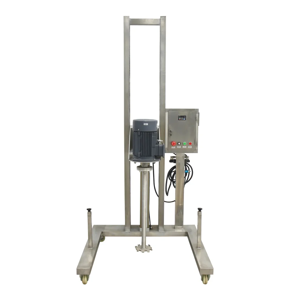
Pneumatic Lifting High Speed Disperser Mixer with Stainless Steel Frame for Paint, Ink, Coating & Pigment
View Details

Working Principle
The process begins with a compatible batch vessel positioned and restrained beneath the mixing head. Operators charge the initial liquid according to the approved formulation sequence. Before starting, the dispersion disc must be at an approved position within the liquid, with sufficient clearance from the vessel walls and bottom.
The electric drive rotates the shaft and saw-tooth disc. Rotation creates liquid movement around the disc and shear near its working edge. Under suitable conditions, this action helps wet incoming powders, distribute particles and break down compatible agglomerates. Effective processing depends on the relationship between disc diameter, rotational speed, vessel geometry and product behavior.
Powders or additional liquids enter at a controlled rate appropriate to the batch response. Operators adjust speed within the approved operating range as solids loading and viscosity change. Excessive surface disturbance, air incorporation, splash and rising product temperature indicate conditions that require review rather than an automatic increase in speed.
Processing continues until the batch meets its agreed checks, such as appearance, dispersion quality or another formulation-specific endpoint. The disperser does not establish a universal particle size or processing duration, and some products require a separate downstream milling stage.
After processing, the shaft must stop completely before the head is raised under the approved operating procedure. The batch then moves to its next stage through the separately defined vessel-discharge or transfer arrangement. Hydraulic lifting provides access between operations; it is not a discharge mechanism or permission to operate an exposed rotating disc.
Optional Upgrades & Configurations
| Warranty | 24 Months | Payment Terms | 40% T/T Deposit, 60% Balance Before Shipment (Alibaba Trade Assurance Available) |
| Lead Time | In Stock | Packaging | Standard Export Fumigation-Free Wooden Case |
After-Sales & Technical Support
🔧 Common Problems
Possible observable symptoms include persistent powder floating on the surface, visible agglomerates after processing, sediment or streaks in samples, weak circulation in part of the vessel, excessive surface vortexing, foaming, retained air, splashing, unexpected temperature rise, or inconsistent results between batches. Operators may also observe abnormal shaft vibration, unusual drive noise, unstable speed response, motor or VFD trips, worn or damaged disc teeth, difficulty raising or lowering the head, uneven lifting movement, hydraulic oil seepage, or visible residue remaining after cleaning. These are potential observations rather than confirmed machine defects. Record the batch stage, vessel, disc, speed setting and material condition when a symptom occurs so that service personnel can review the operating circumstances.
🛠 Troubleshooting
Problem: Powders remain floating or form visible agglomerates. Possible Cause: The addition rate, disc position or operating settings do not suit the formulation. Recommended Solution: Review the approved charging sequence. Check vessel geometry and disc immersion before increasing speed or extending processing.Problem: The batch develops excessive foam or splashing. Possible Cause: Surface disturbance is too strong for the liquid level or material addition stage. Recommended Solution: Return to the approved operating conditions. Review speed, fill level and charging method without operating outside the permitted disc position.Problem: The shaft vibrates or the disc produces abnormal noise. Possible Cause: Product loading, inadequate clearance, deposits or damaged rotating components. Recommended Solution: Stop the drive. Isolate the machine before checking the disc, attachment and shaft condition. Obtain qualified service support before restarting.Problem: The drive trips during processing. Possible Cause: Overloading, a mechanical restriction or an electrical fault. Recommended Solution: Record the fault code and batch stage. Arrange qualified investigation rather than repeatedly resetting the protection.Problem: The head lifts slowly or moves unevenly. Possible Cause: An operating obstruction, unsuitable hydraulic oil condition or a hydraulic-system fault. Recommended Solution: Stop lifting. Inspect accessible conditions according to the hydraulic instructions. Do not loosen pressurized connections.Problem: Hydraulic oil appears around a connection. Possible Cause: A connection or sealing component requires inspection. Recommended Solution: Stop operation and make the system safe. Have qualified personnel identify the leakage point before tightening or replacing matched components.
🧼 Cleaning Method
1. Stop the dispersion drive at the end of the approved batch process. 2. Confirm complete shaft standstill before operating the lifting function. 3. Raise the head only to the approved cleaning-access position. 4. Secure the raised assembly using the manufacturer's approved maintenance-support method. 5. Isolate the electrical supply under the site's lockout procedure before manual cleaning access. 6. Recover accessible product residue using a method compatible with the formulation and disc geometry. 7. Apply an approved cleaning medium selected for the residue and installed materials. 8. Clean the accessible shaft surfaces without damaging their finish. 9. Clean the disc teeth using suitable tools while avoiding direct contact with sharp edges. 10. Remove the disc only when the approved cleaning procedure requires separate component access. 11. Clean the detached disc according to its approved handling and cleaning instructions. 12. Remove cleaning-agent residue to the acceptance standard specified for the next product. 13. Inspect the cleaned shaft and disc for retained material before reassembly. 14. Refit the disc according to the approved attachment instructions. 15. Release the workstation for production after the required cleaning checks are complete.
📋 Maintenance
1. Isolate the machine under the approved lockout procedure before preventive maintenance. 2. Support the raised head using the manufacturer's approved method before working beneath it. 3. Inspect the dispersion disc for damaged teeth, distortion or uneven wear. 4. Inspect the disc attachment for deterioration according to its service instructions. 5. Examine the accessible shaft surfaces for deposits, damage or corrosion. 6. Check the drive-bearing condition through the manufacturer's approved inspection method. 7. Lubricate serviceable components using only the specified lubricant and application method. 8. Inspect accessible hydraulic hoses for abrasion, cracking or visible leakage. 9. Check the hydraulic oil condition according to the hydraulic-system service instructions. 10. Inspect the lifting guides for contamination or deterioration. 11. Examine the painted frame for coating damage that requires maintenance. 12. Arrange qualified inspection of electrical terminals and protective devices. 13. Verify the function of the installed stop controls through the approved functional-check procedure. 14. Record maintenance findings against the machine serial number and operating history. 15. Schedule corrective service for deteriorated parts before releasing the machine for further use.
⚙️ Installation
1. Review the final installation drawing before preparing the workstation. 2. Confirm the fully raised operating envelope against the available building clearance. 3. Obtain approval of the floor and anchoring arrangement for the complete operating installation. 4. Inspect the delivered machine for visible transport damage. 5. Position the machine using the manufacturer's designated handling arrangement. 6. Level the frame according to the approved installation instructions. 7. Secure the floor mounting according to the approved anchoring design. 8. Position the compatible vessel within the specified shaft and disc operating envelope. 9. Install the approved vessel-restraint arrangement. 10. Arrange electrical connection by qualified personnel using the final wiring documentation. 11. Verify protective earthing before electrical commissioning. 12. Check the hydraulic oil specification against the lifting-system documentation. 13. Commission the hydraulic lift according to the manufacturer's approved procedure. 14. Verify the installed guards and operating protections against the agreed configuration. 15. Perform the approved liquid trial with the disc at a permitted operating position. 16. Document the representative-product test against the agreed acceptance criteria before routine production.
🔩 Spare Parts
Why Choose This Machine
- Focused dispersion duty: The saw-tooth disc provides a practical processing option for suitable paint, coating, ink and chemical batches that require powder wetting and dispersion.
- Adjustable processing intensity: Variable-speed operation allows the approved settings to change between initial charging, solids incorporation and final blending rather than imposing one speed throughout the batch.
- Accessible tooling: The lifting head and removable disc support inspection and approved tooling changes without treating every product as requiring the same disc geometry.
- Defined workstation layout: Floor mounting allows the machine, vessel position and ingredient-handling area to be planned as a dedicated production station.
- Operator-led production: Push-button controls suit documented manual processing sequences where operators manage ingredient addition and assess batch response.
- Application-specific selection: The listed batch capacity can be evaluated together with solids loading, vessel geometry and the required result, helping buyers avoid selection by motor power alone.
Frequently Asked Questions
Installation Requirements
The machine weighs approximately 500 kg. Assess the floor and anchoring requirements against the complete installation, including the vessel, product load and applicable operating loads. Allow space for vessel handling, ingredient charging, cleaning, maintenance and withdrawal of the stopped shaft.
Confirm the electrical supply against the final motor, VFD and hydraulic power-unit schedule. The listed total power is 9 kW. Qualified personnel must determine cable sizing, circuit protection and protective earthing. The configurable voltage range describes available supply configurations, not the operating range of one delivered machine.
No process heating or cooling system is specified. Confirm any hydraulic service requirements from the equipment documentation. Compressed air is only required if an explicitly selected auxiliary function uses it.
Define the vessel restraint, guarding and operating protections before commissioning. Assess powder extraction, ventilation and any hazardous-area requirements against the actual materials. Provide suitable cleaning access without exposing unprotected electrical or hydraulic components to wash water.
Related Articles



Technical Buyer's Handbook & Deep Insight
Ready to Get a Quote?
Contact our team directly for pricing, customization options, and delivery timelines.
💬 WhatsApp Us NowGet Your Download Link
Please fill in your details and we'll send the download link to your email.