

300L Vacuum Mayonnaise Emulsifying Machine with 3-Stage Inline Homogenizer & Oil Water Tanks for Salad Dressing, Ketchup & Sauce Processing
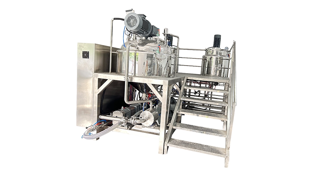
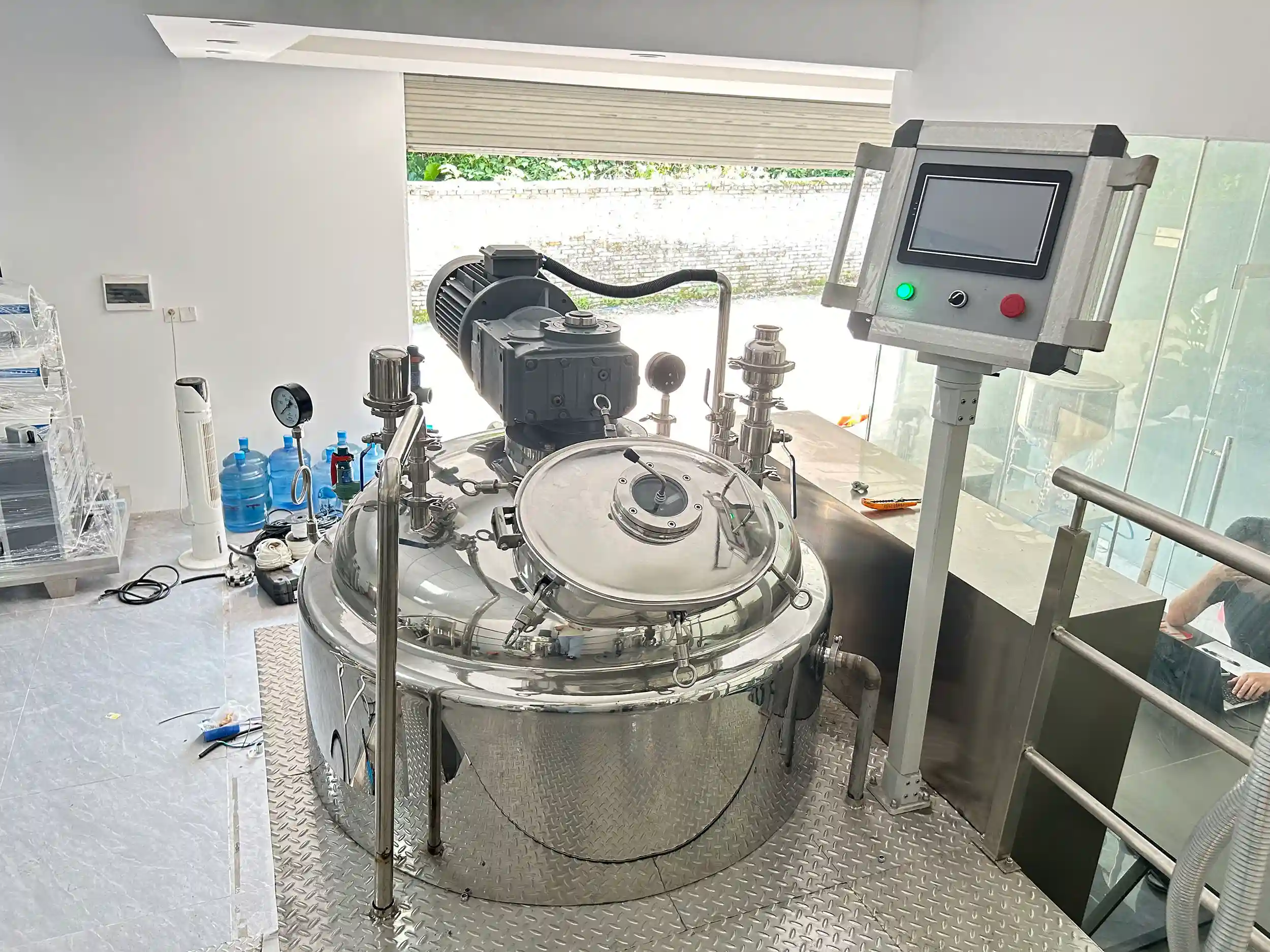
The 300L Vacuum Mayonnaise Emulsifying Machine is a fixed-head batch system for compatible mayonnaise, salad dressing, ketchup and sauce formulations. It combines scraped vessel agitation with a standard circulation lobe pump and three-stage inline homogenizer. Within the vacuum emulsifying mixers range, this model provides separate phase preparation, thermal processing and a defined external emulsification circuit under PLC/HMI control.
- Conical Bottom, Lobe Rotor Pump & Circulation Pipeline for High Viscosity Food Emulsions
| Total Capacity (L) | 360 | Vacuum Pump Brand | High-quality domestic/joint venture brands |
| Working Capacity (L) | 300 | Discharge Method | Bottom Valve Discharge (Optional Rotor Pump) |
| Min Batch Size (L) | 100 | Discharge Valves | Flush Bottom Valve |
| Structure Type | Triple Layer (with Jacket & Insulation) | Mechanical Seal Brand | Single Mechanical Seal (John Crane/EagleBurgmann Optional) / Double Mechanical Seal (EagleBurgmann) |
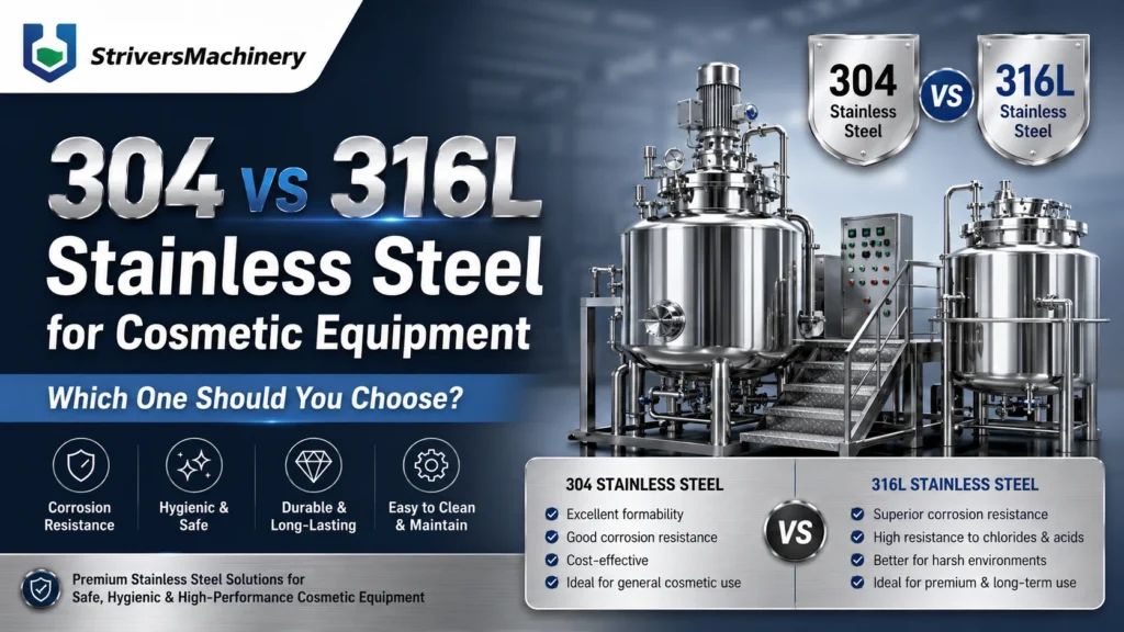
| Contact Material | SUS304 Stainless Steel | Types of Upper Heads | Torispherical (Dish) Head / Fixed Top Head |
| Non-contact Material | SUS304 Stainless Steel | Top Openings & Accessories | Vacuum Port / Vacuum Feeding Port / Powder Feeding Port / Liquid Inlet / Fragrance Addition Port / Manway / Sight Glass with Wiper / LED Inspection Light / CIP Spray Ball / Vent Filter / Vacuum Gauge / Pressure Sensor / Compressed Air Inlet |
| Surface Finish | Interior Mirror Polish (Ra ≤ 0.4 μm) & Exterior Satin/Matte Finish | Motor Brand | SEW / ABB / Siemens / Top-Tier Chinese Brands (Optional) |
| Jacket Design Pressure (MPa) | 0.3 | vem_electrical_components | Schneider / Siemens / Omron (Optional/Customizable) |
| Main Tank Mixer Type | Gate Agitator + Single/Dual Fixed Paddles | Oil & Water Pot | Equipped with Integrated Oil & Water Pre-treatment Pots |
| Mixing Speed (rpm) | 0–63 rpm | Oil & Water Pot Capacity (L) | Oil: 150 L / Water: 240 L |
| Mixing Motor Power (kW) | 4 | Explosion Proof | Standard Non-Explosion Proof (For Regular Cosmetics) |
| Frequency Control | Variable Speed with VFD (Delta, Siemens, ABB, Schneider, Optional) | Platform & Ladder | SUS Anti-slip Platform with Guardrails & Ladder |
| Scraper System | Wall-Scraping PTFE Scrapers | Voltage | Configurable to local grid (110V–480V, 50/60Hz, Single or 3-Phase) |
| Homogenizer Position | External Inline Recirculating Homogenizer | Total Power (kW) | 22 |
| Homogenizer Type | Multi-Stage High Shear Mixer | Air Pressure | 0.4–0.8 MPa |
| Homogenizer Power (kW) | 15 | Drive Type | Electro-Pneumatic Combined |
| Homogenizer Speed (rpm) | 0–3000 rpm (Variable Speed) | Installation Type | Platform-mounted |
| Max Processing Viscosity (mPa·s / cP) | 50,000 | Automation Level | Fully Automatic |
| Heating Method | Electric Heating via Jacket / External Steam Heating (Optional) | Control System | PLC + HMI Touch Screen Control |
| Cooling System | Tap Water / Cooling Tower Circulation (Chilled Water / Glycol Circulation Optional) | PLC System | Siemens |
| Water Chiller | External Water Chiller Unit (Optional) | HMI / Touch Screen | Siemens |
| Temperature Control Accuracy | ±1°C | Machine Dimensions(L*W*H)mm | 2100*1500*2200 |
| Vacuum Degree (MPa) | -0.09 | Machine Weight (kg) | 1500 |
Product Gallery
Product Video
Product Overview
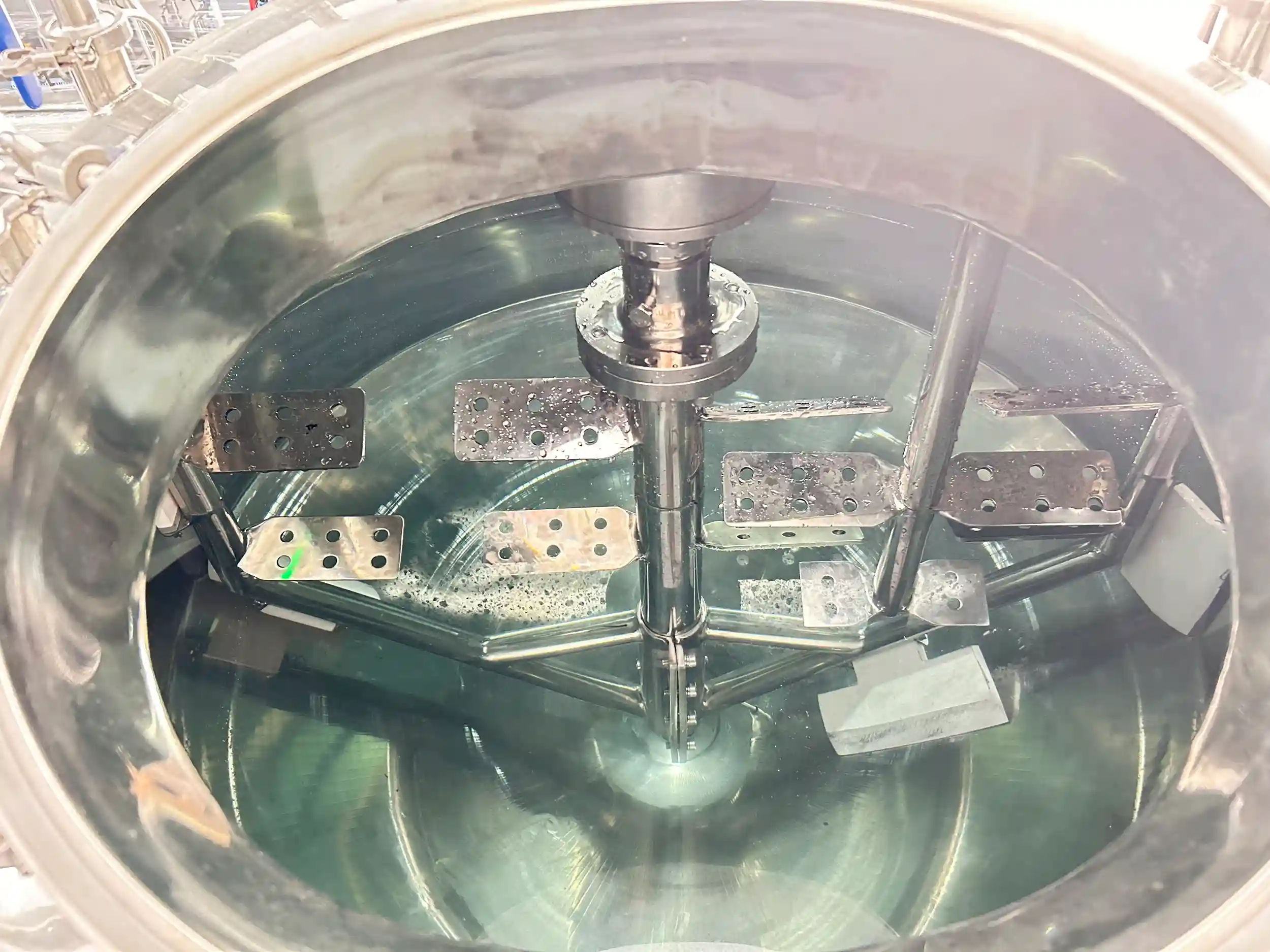
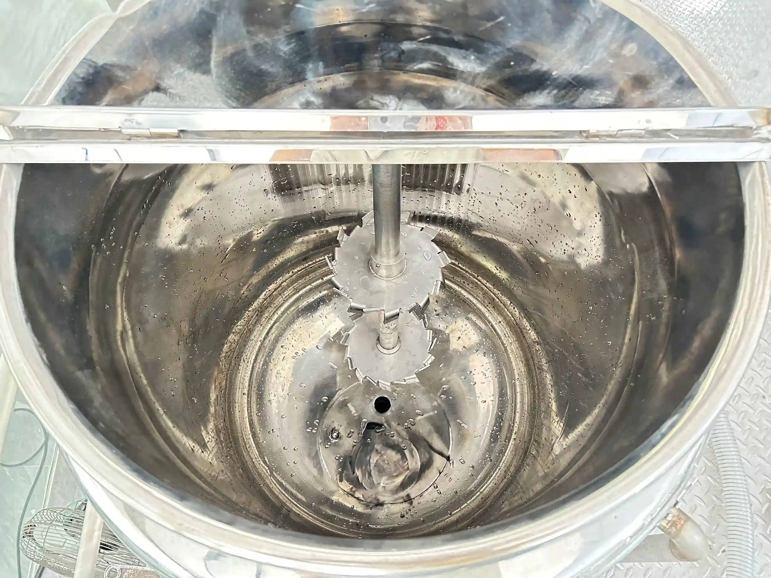
This machine provides a coordinated preparation platform for compatible food emulsions and sauces. Its main vessel combines gate agitation, PTFE wall scraping, vacuum provision and a heating-and-cooling jacket. Separate oil and water pots support formulation-specific ingredient preparation before transfer into the main batch.
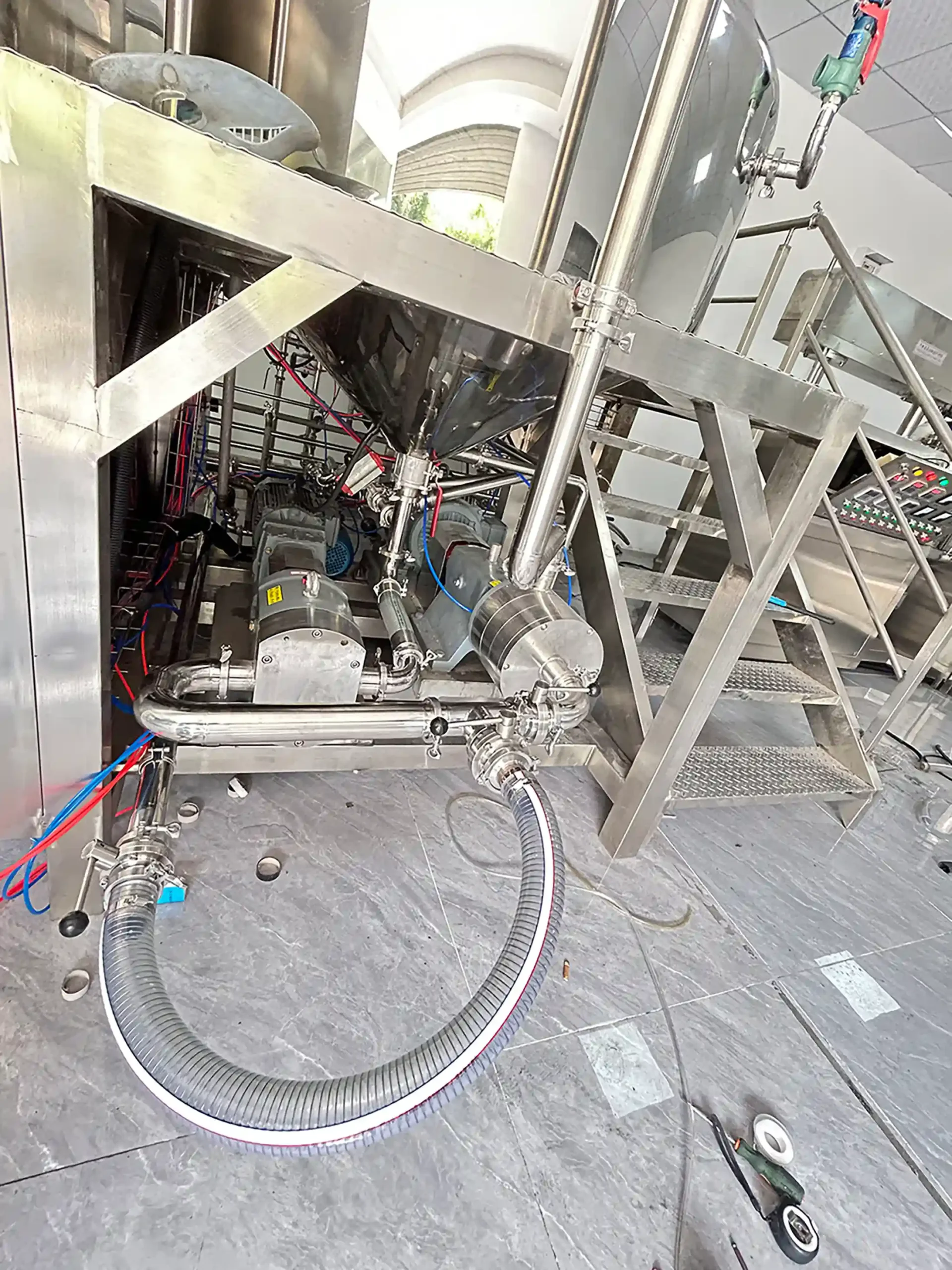
For mayonnaise, salad dressing and sauce processing, the external circuit gives the product a defined route through the inline homogenizer. A standard lobe rotor pump draws material from the conical-bottom vessel, feeds it through the three-stage working assembly and returns it to the main tank.
The circulation pump and inline homogenizer perform different duties: the pump provides product movement through the circuit, while the homogenizer applies high shear. Neither function replaces the main agitator’s role in distributing material within the vessel.
Siemens PLC and HMI provide the specified control platform. The delivered automatic sequence, ingredient-addition method and operator tasks should be documented in the agreed functional schedule.
Finished product leaves through the flush bottom valve. A separate discharge rotor pump is optional and should not be confused with the included circulation pump. SUS304 product-contact construction requires compatibility review against the actual ingredients, temperatures and cleaning chemicals.
Machine Configuration
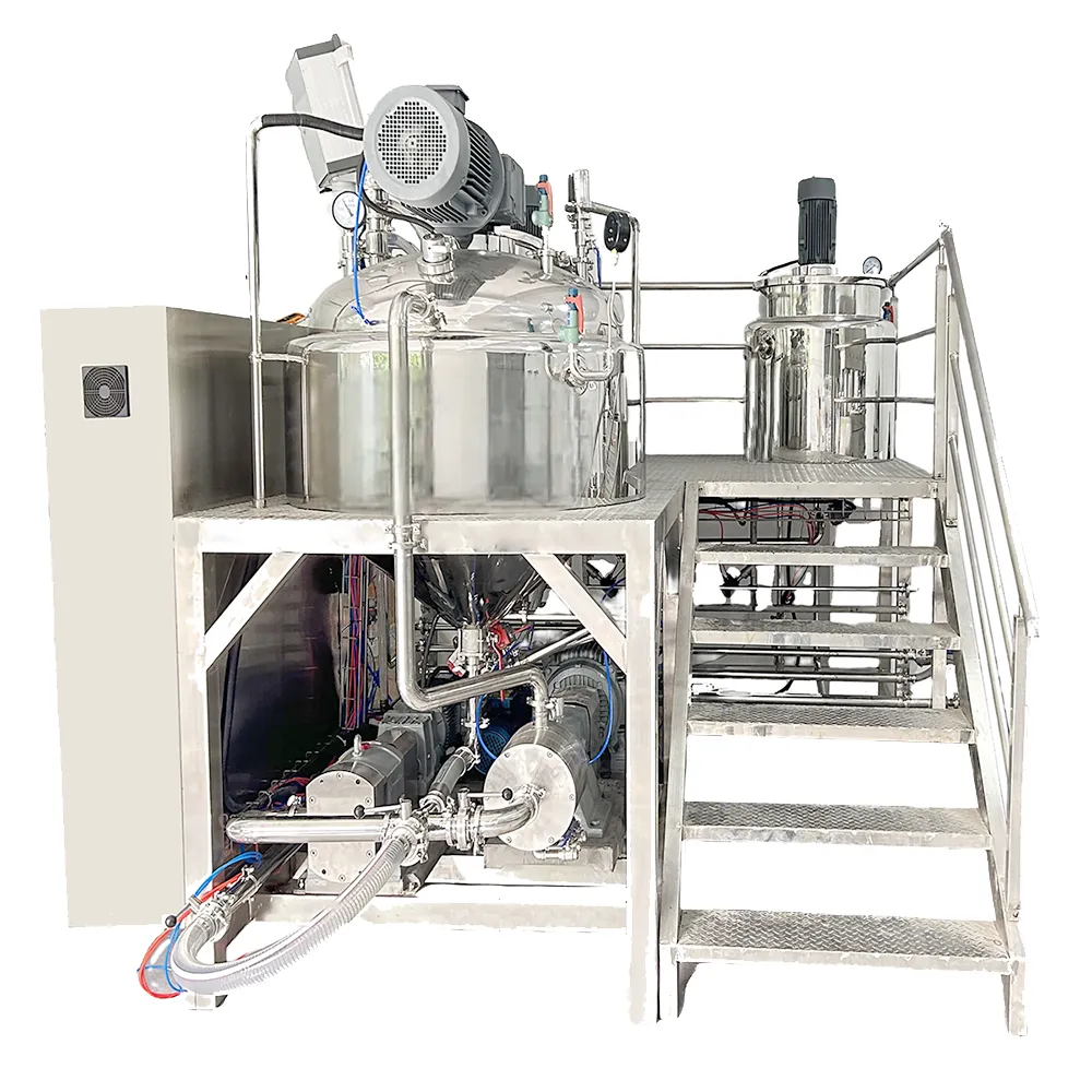
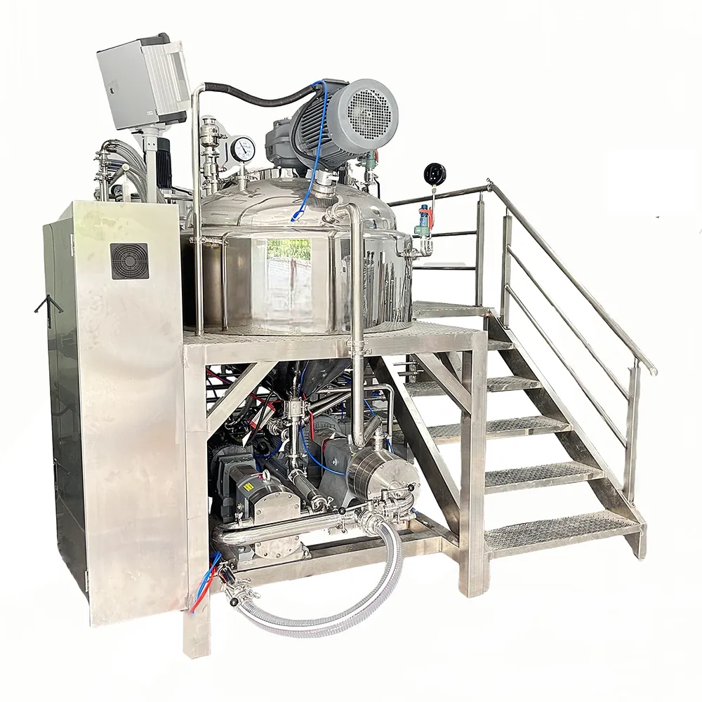
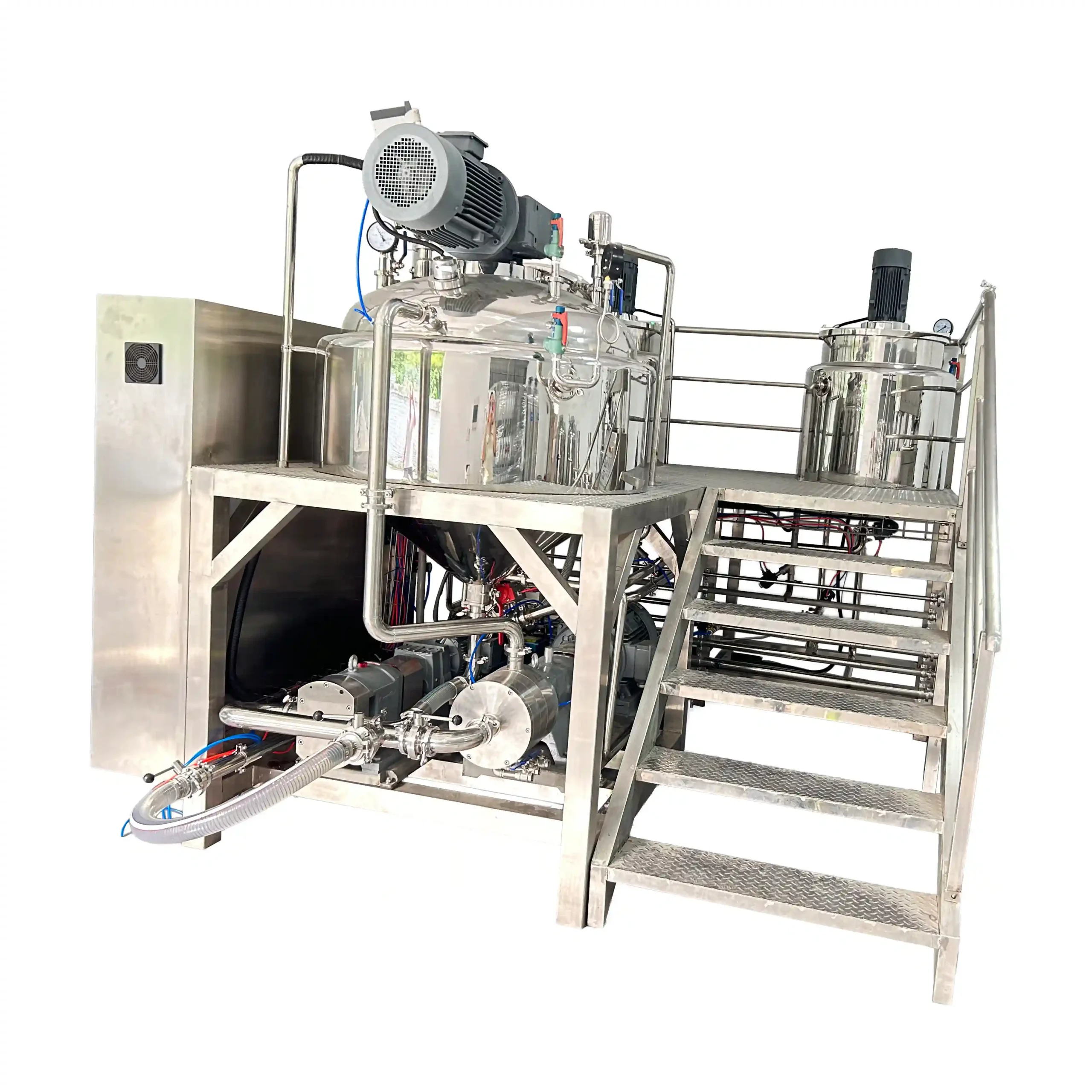
The main assembly includes a jacketed and insulated vessel with a conical bottom, fixed dished top head, gate agitator, fixed paddles and PTFE wall scrapers. Integrated oil and water pots provide separate ingredient-preparation capacity.
The external processing circuit comprises the standard circulation lobe pump, three-stage inline homogenizer and return pipework. Product flows from the main-vessel bottom through the pump and homogenizer before returning to the tank.
The jacket connects to the selected electric-heating or optional steam arrangement and the approved cooling-water service. The vacuum system connects through the designated vessel ports.
Siemens PLC and HMI coordinate the supplied functions through the agreed program. The flush bottom valve serves the discharge arrangement, with a separate discharge rotor pump optional. The platform, guardrails and ladder provide access. Final drawings should identify circuit routing, valve positions, cleaning access and the selected seal-support services.
Key Features
- A standard circulation lobe pump feeds the external homogenizing circuit.
- Three-stage inline processing provides successive high-shear zones within the working assembly.
- External return pipework connects the homogenizer outlet back to the main vessel.
- Scraped bulk agitation complements the separate pump-fed emulsification stage.
- Integrated oil and water pots support formulation-specific phase preparation.
- Jacketed construction accommodates the selected heating and cooling duties.
- Conical-bottom geometry directs material toward the lower vessel outlet.
- A flush bottom valve provides a defined discharge connection.
- Siemens PLC and HMI support the agreed automatic processing functions.
Applications
- Sauce, Condiment & Food Paste
Recommended Machines

100 LITERS Hydraulic Lift Vacuum Emulsifying Machine for Cream, Lotion & Cosmetic Production
View Details
20L Laboratory Vacuum Emulsifying Mixer for Cosmetic Cream, Lotion, Gel, Ointment, Shampoo, Toothpaste and Pharmaceutical Products
View Details

Working Principle
Production begins with ingredient preparation according to the approved formulation. The oil and water pots support separate preparation where required, while other ingredients may enter the main vessel through designated charging connections.
The gate agitator establishes bulk movement within the main tank. PTFE scrapers act along the vessel wall, and the jacket supplies the selected thermal duty. These functions help establish the product condition required for incorporation and emulsification.
The circulation lobe pump draws product from the bottom of the main vessel and feeds it to the external inline homogenizer. Material passes through three successive high-shear stages before returning through the circulation pipework to the tank.
The ingredient-addition sequence and rate must match the formulation and processing capability. The three-stage arrangement does not mean that every portion of the batch receives exactly three total treatments: material can circulate repeatedly, and its exposure depends on actual flow, mixing and operating duration.
Vacuum is applied during the stages defined by the process. The PLC program coordinates the supplied functions, while operators complete any separately identified charging, sampling or authorization tasks.
After the batch reaches its accepted condition, finishing additions and cooling proceed as required. Product leaves through the flush bottom valve, using a separate discharge rotor pump if selected. The circulation and discharge routes must follow the approved valve arrangement rather than being treated as interchangeable pathways.
Optional Upgrades & Configurations
| Warranty | 24 Months | Payment Terms | 40% T/T Deposit, 60% Balance Before Shipment (Alibaba Trade Assurance Available) |
| Lead Time | 15–20 Working Days | Packaging | Standard Export Fumigation-Free Wooden Case |
Recommended Accessories


After-Sales & Technical Support
🔧 Common Problems
Possible observable symptoms include uneven product appearance, visible oil separation, persistent agglomerates, inconsistent sample texture, excessive foam, retained air or unexpected viscosity changes. Circuit-related observations may include weak or intermittent return flow, unusual pressure indications, abnormal lobe-pump or homogenizer noise, vibration, drive trips or leakage around a seal or connection. Operators may also observe difficulty reaching the intended vacuum condition, unexpected pauses in the automatic sequence, slow discharge or retained material after emptying. Cleaning may leave visible residue in valve areas, working-head components or part of the return route. These are potential observations rather than confirmed defects. Record the ingredient stage, batch quantity, temperatures, valve positions and operating settings when investigating a symptom.
🛠 Troubleshooting
Problem: Oil separation or uneven texture appears. Possible Cause: Ingredient preparation, addition conditions, circulation or shear exposure differ from the approved process. Recommended Solution: Review the batch record and sampling conditions. Assess the complete sequence before increasing speed or processing time.Problem: Return flow becomes weak or intermittent. Possible Cause: Incorrect valve routing, inadequate pump supply, changing viscosity or a circuit restriction. Recommended Solution: Review the approved operating route and product conditions. Stop and isolate the equipment before investigating restrictions.Problem: The lobe pump or homogenizer produces abnormal noise. Possible Cause: Unsuitable operating conditions, foreign material or a mechanical fault. Recommended Solution: Stop the affected circuit. Obtain qualified inspection before restarting or replacing components.Problem: Vacuum remains below the intended condition. Possible Cause: An open vent, incorrectly seated connection, foaming or a vacuum-system fault. Recommended Solution: Review accessible settings and product behavior. Arrange inspection of the sealing and vacuum assemblies.Problem: The automatic sequence pauses unexpectedly. Possible Cause: A required process condition, confirmation or operating permission is absent. Recommended Solution: Review the HMI message and agreed functional schedule. Correct the identified condition without bypassing protections.Problem: Residue remains after cleaning. Possible Cause: Cleaning routing or access does not reach the affected surfaces. Recommended Solution: Review the approved route through the pump, homogenizer and return pipework before repeating cleaning.
🧼 Cleaning Method
1. Recover the remaining product through the approved discharge arrangement. 2. Bring the system to the safe temperature specified for cleaning access. 3. Equalize vessel pressure through the approved procedure before opening connections. 4. Isolate energy sources under the site's lockout procedure before manual access. 5. Configure the approved cleaning route through the main vessel and external circuit. 6. Pre-rinse the product-contact pathway with a medium suitable for the residue. 7. Apply the approved cleaning agent under the specified cleaning conditions. 8. Clean the main vessel through the supplied spray provision using the approved supply arrangement. 9. Clean the circulation lobe pump according to its component instructions. 10. Clean the three-stage inline homogenizer through its approved cleaning or service-access method. 11. Clean the return pipework through the designated route. 12. Clean the auxiliary pots according to their individual procedures. 13. Clean designated detachable valve and connection components separately where required. 14. Rinse until the specified cleaning-agent acceptance criteria are met. 15. Sanitize the system when the validated product-changeover procedure requires it. 16. Inspect accessible areas for retained residue before reassembly. 17. Release the system after the required cleaning checks are complete.
📋 Maintenance
1. Isolate the system under the approved lockout procedure before preventive maintenance. 2. Equalize vessel pressure through the approved method before opening service connections. 3. Confirm a safe product-contact temperature before accessing components. 4. Inspect the gate agitator and fixed paddles for visible damage. 5. Examine PTFE scrapers for wear, deformation or damaged attachments. 6. Inspect lobe-pump wetted components during approved service access. 7. Inspect the three-stage working assembly according to the homogenizer service instructions. 8. Check the installed mechanical seals for leakage or deterioration. 9. Maintain seal-support services according to the selected component documentation. 10. Examine product-contact gaskets for damage or chemical attack. 11. Inspect circulation pipework and supports for visible deterioration. 12. Service the vacuum pump according to its manufacturer's schedule. 13. Inspect accessible heating and cooling connections for leakage. 14. Arrange qualified inspection of electrical terminals and protective devices. 15. Verify process instruments under the site's approved checking procedure. 16. Verify the supplied stop functions and operating protections through the approved test method. 17. Record maintenance findings against the machine and component identification.
⚙️ Installation
1. Review the approved general arrangement and circulation drawings before preparing the site. 2. Verify the delivery route against the transport envelope and handling requirements. 3. Obtain approval of the floor and supports for the complete operating loads. 4. Inspect the delivered equipment for visible transport damage. 5. Position the assemblies using the manufacturer's designated lifting arrangement. 6. Level the supports according to the installation instructions. 7. Secure the equipment according to the approved support design. 8. Assemble the platform access structure according to the supplied drawings. 9. Connect the main-vessel outlet to the circulation lobe pump. 10. Connect the pump discharge to the three-stage inline homogenizer. 11. Connect the homogenizer outlet to the approved main-vessel return point. 12. Connect the selected heating and cooling services. 13. Connect required vacuum-pump and mechanical-seal support services. 14. Connect the regulated compressed-air supply according to the pneumatic schedule. 15. Install any separate optional discharge pump according to its instructions. 16. Arrange electrical connection by qualified personnel using the final wiring documentation. 17. Verify protective earthing before electrical commissioning. 18. Commission the supplied functions against the approved control schedule. 19. Perform the approved liquid test of circulation and connected services. 20. Document the representative-product trial against the agreed acceptance criteria before routine production.
🔩 Spare Parts
Why Choose This Machine
- Defined external processing route: The included circulation pump and return pipework establish a reviewable circuit from the vessel through the inline homogenizer and back.
- Separate pumping and shearing duties: Product movement and high-shear processing are assigned to distinct components, allowing their operating relationship to be assessed against the actual formulation.
- Complementary vessel mixing: Gate agitation and scraping address bulk movement and the wall region while the external system processes the circulating stream.
- Integrated phase preparation: Oil and water pots support recipes requiring separate preparation without assuming one universal ingredient sequence.
- Coordinated control platform: Siemens PLC and HMI provide the specified basis for the agreed automatic functions and operator interface.
- Separate discharge selection: The optional discharge pump can be matched to the finished product and receiving equipment without being confused with the standard circulation pump.
Frequently Asked Questions
Installation Requirements
The listed machine weight is 1500 kg. Assess floor and support requirements using the complete operating loads, including product in the main vessel, auxiliary pots and circulation circuit. Calculate material mass from the actual densities.
Confirm the electrical supply against the final heater, agitator, homogenizer, circulation-pump, vacuum-pump and control-panel schedule. The listed total power is 22 kW. Qualified personnel should determine protection, cable sizing and earthing from the approved load schedule.
Provide the selected heating and cooling services with defined operating conditions. Optional steam heating requires an engineered supply, regulation and condensate arrangement. The 0.3 MPa jacket design pressure is not a product-vessel pressure rating.
Provide compressed air at the specified 0.4–0.8 MPa supply range for the included pneumatic functions. Confirm air quality, consumption and regulation from the final schedule.
Define vacuum-pump and mechanical-seal support services using the selected component documentation. Provide cleaning-water access, drainage and access to the entire circulation route. Include any optional discharge pump or chiller in the layout and utility assessment.
Related Articles


Technical Buyer's Handbook & Deep Insight
Ready to Get a Quote?
Contact our team directly for pricing, customization options, and delivery timelines.
💬 WhatsApp Us NowGet Your Download Link
Please fill in your details and we'll send the download link to your email.