
1000LPH Double Pass Reverse Osmosis Water Treatment System with Stainless Steel Pretreatment Tanks & Storage Tanks for Cosmetics, Pharma & Food
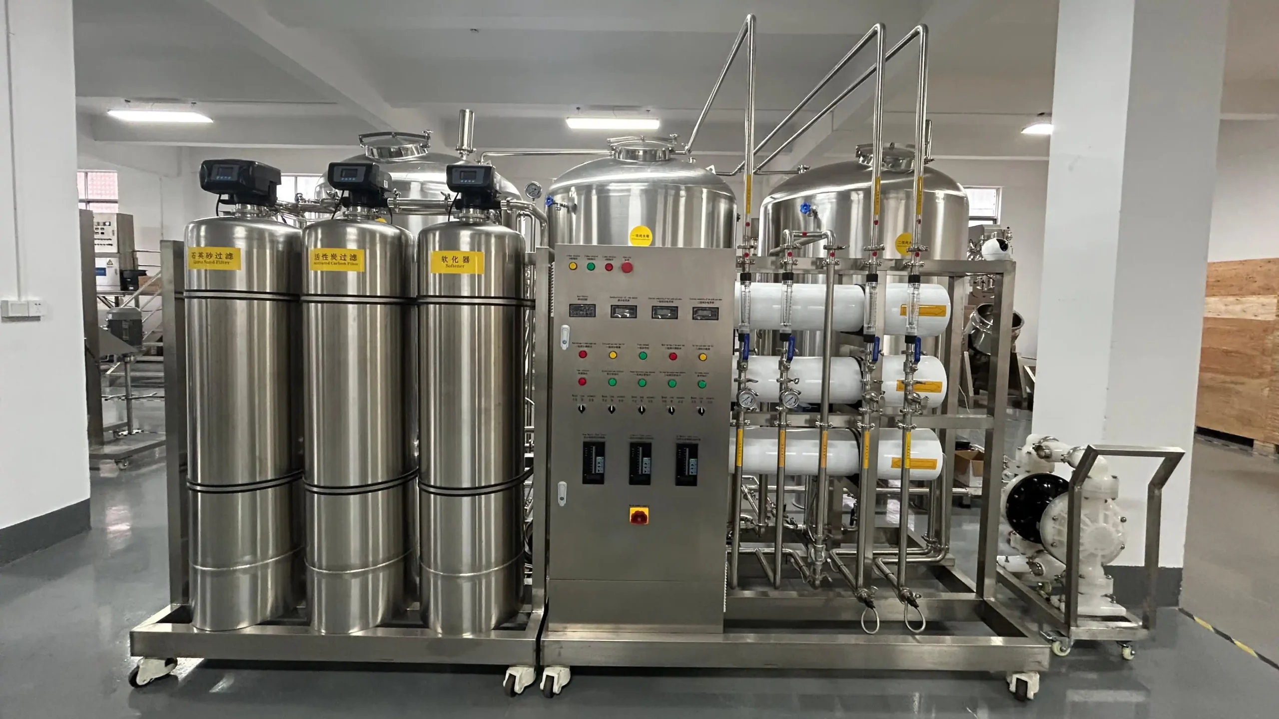
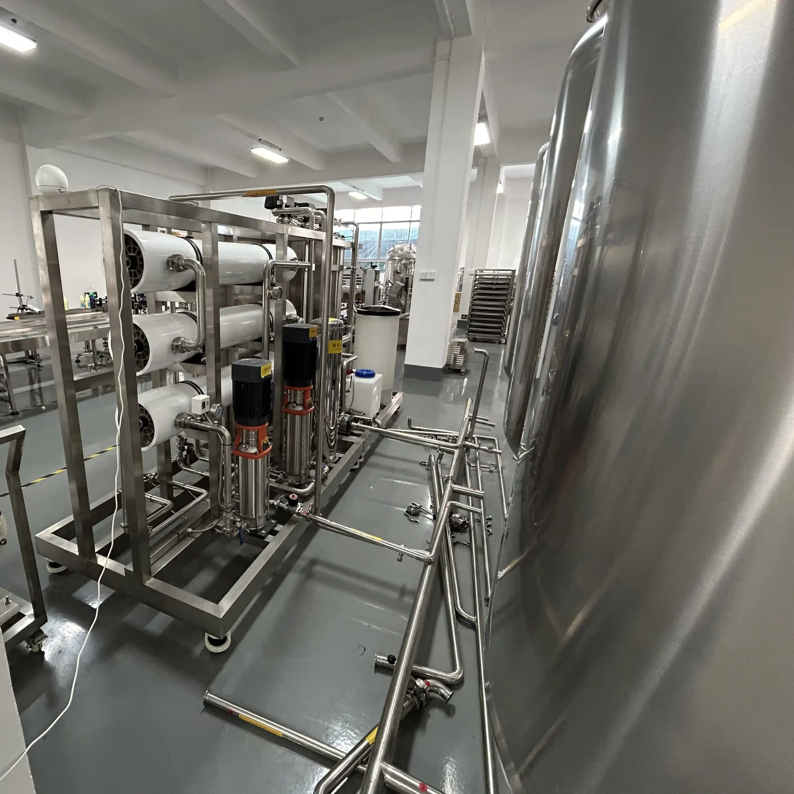
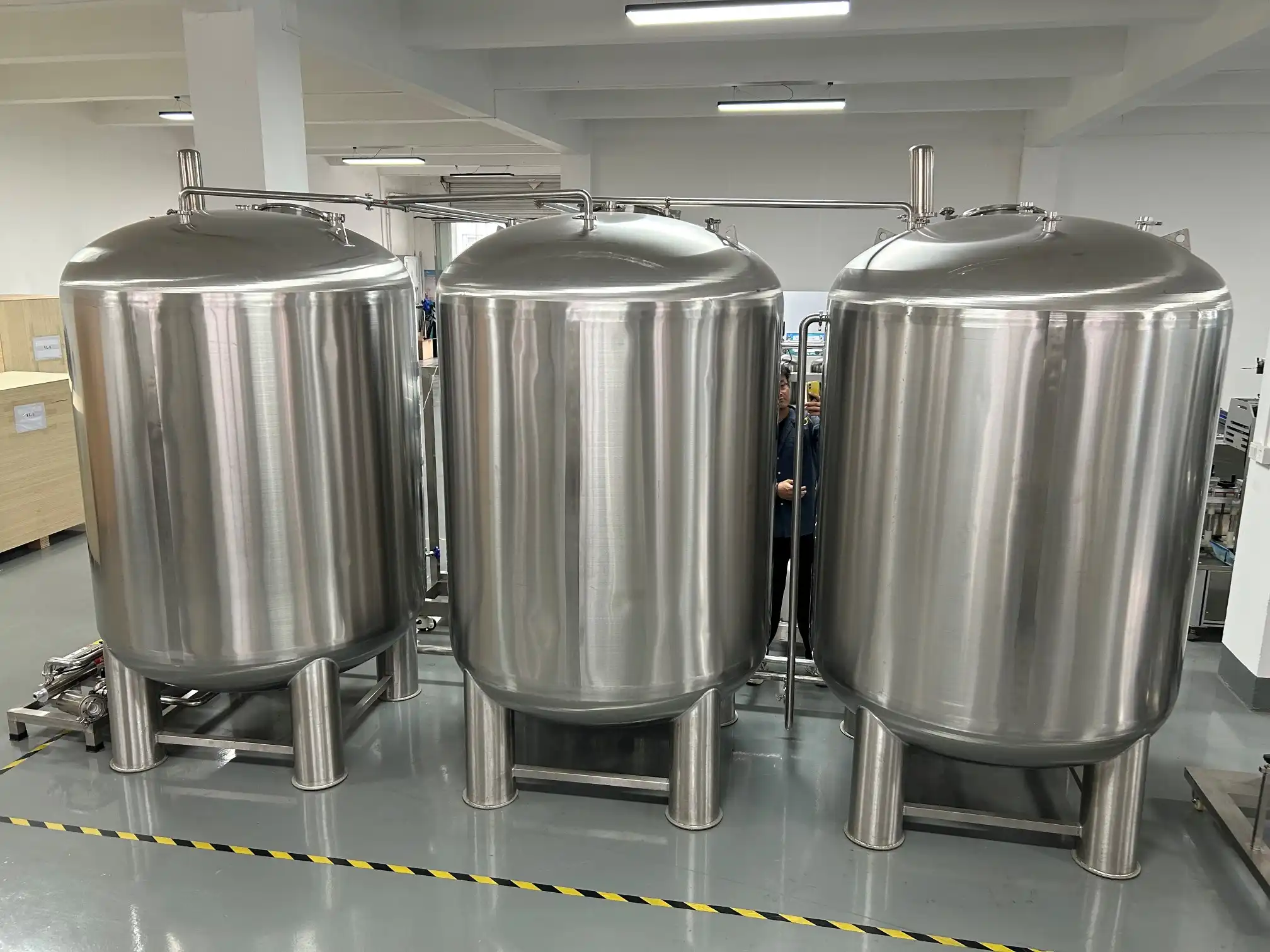
The 1000LPH Double Pass Reverse Osmosis Water Treatment System is a process-water preparation unit for cosmetic, food and selected pharmaceutical manufacturing requirements. It combines pretreatment, two-pass membrane separation and stainless steel water storage upstream of production equipment. Within the water treatment systems range, this configuration serves manufacturers evaluating reduced-conductivity water against defined production and quality requirements.
| Production Capacity (L) | 1000 | Pipe Material | SUS304 Stainless Steel |
| Water Source | Municipal Tap Water / Deep Well Water / Underground Water | Operating Pressure (MPa) | 0.2 – 1.5 |
| Purification Process | RO (Reverse Osmosis) | Working Temperature | 5 – 45°C (41–113°F) |
| RO Stage | Double Stage RO (2-Pass) | Voltage | Configurable to local grid (110V–480V, 50/60Hz, Single or 3-Phase) |
| Purified Water Conductivity (μS/cm) | 2 | Total Power (kW) | 8 |
| Water Recovery Rate | 50% – 75% | Drive Type | Electric |
| Pretreatment System | Multimedia Sand Filter + Activated Carbon Filter + Water Softener | Installation Type | Mobile (Caster-Mounted) |
| Material of Pretreatment Tanks | SUS304 Stainless Steel | Automation Level | Semi-Automatic |
| Precision Filter | SUS304 Housing with 5μm Cartridge | Electrical Components | Schneider / ABB / Siemens / Omron / Fuji /Mitsubishi (Optional) / Top-tier Chinese Brand: DELIXI / CHINT / People Electric / TENGEN |
| RO Membrane Brand | CSM (Korea) or Chinese High-End Brand (Vontron / Keensen Optional) | Control System | Push Button Control |
| Membrane Housing Material | FRP (Fiber Reinforced Plastic) | Machine Dimensions(L*W*H)mm | 3000mm*2000mm*2000mm |
| High Pressure Pump Brand | CNP (Nanfang Pump) | Machine Weight (kg) | 2000 |
| Storage Tank Material | SUS304 Stainless Steel | ||
Product Gallery


Product Video
Product Overview
Water used as an ingredient or process medium can influence formulation behavior, equipment deposits and finished-product consistency. This system prepares incoming water through pretreatment and two successive reverse osmosis passes before delivery to the specified storage arrangement.
For cosmetic cream, lotion and skin-care manufacturing, the unit can form the upstream water-preparation section of a production line. Water release criteria should reflect the formulation and the factory’s quality-control requirements, including relevant chemical and microbiological checks.
Food-processing and pharmaceutical applications require an application-specific assessment. The supplied configuration does not independently establish potable-water compliance, pharmacopoeial Purified Water quality, sterile water production or suitability for injectable products.
The listed production capacity is 1000 L/h, with a product-water conductivity specification of 2 μS/cm. Feed composition, temperature, operating conditions and the agreed measurement method must accompany these figures when assessing performance.
SUS304 stainless steel is specified for the pretreatment tanks, storage tanks and pipework. The membrane housings are FRP, so the equipment should not be described as an entirely stainless steel system. Semi-automatic push-button control provides the confirmed operating arrangement; automatic regeneration, water-quality diversion and remote monitoring require separate scope confirmation.
Machine Configuration
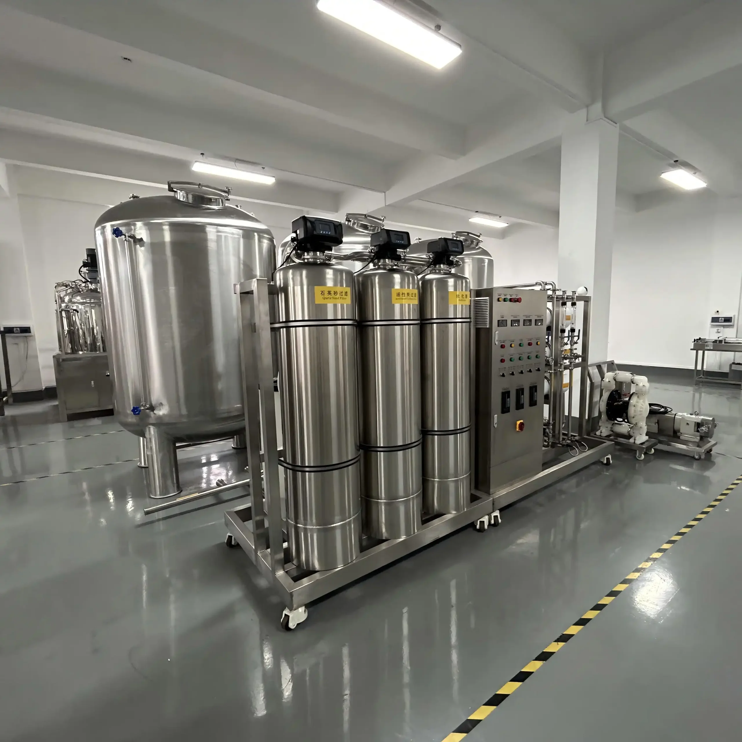
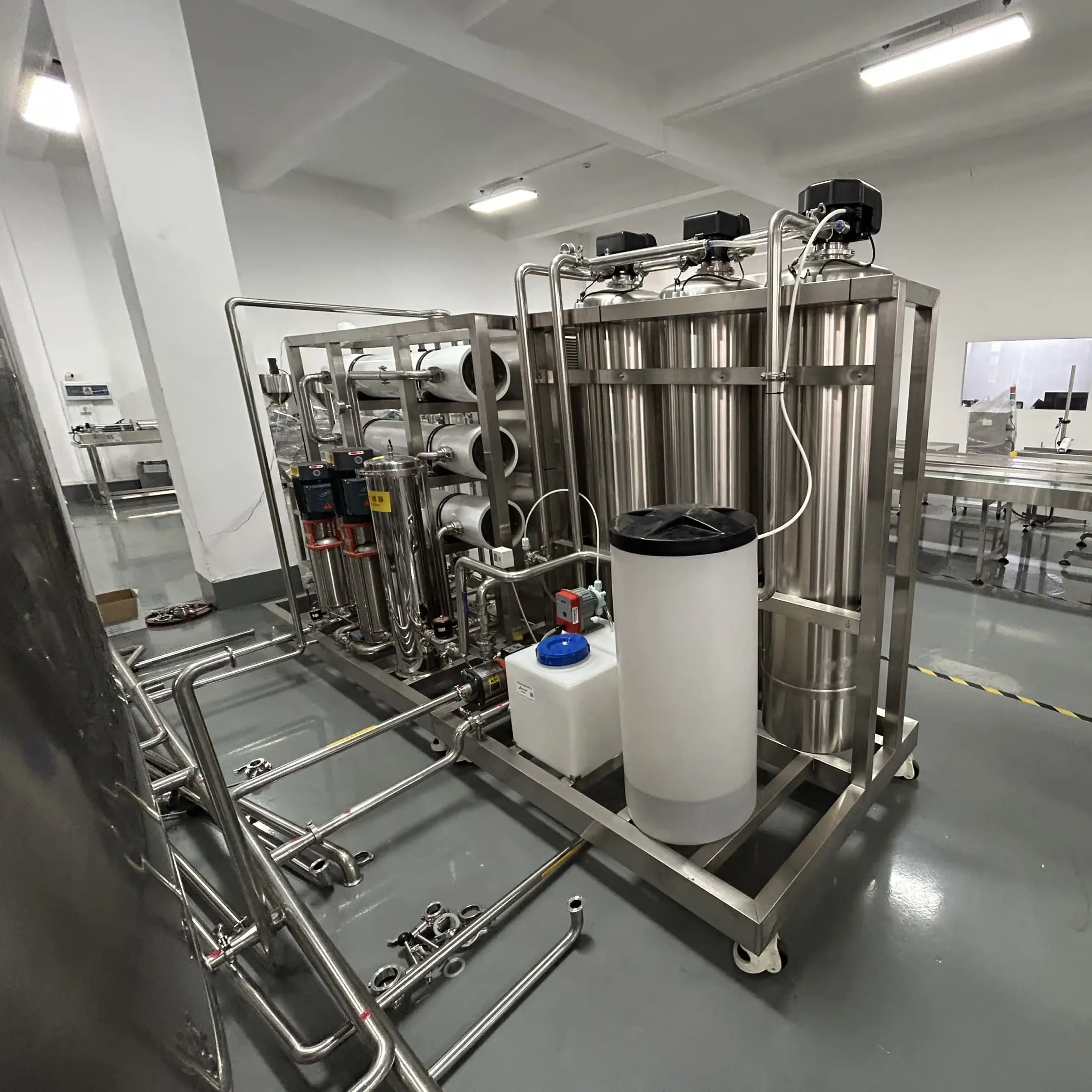
The pretreatment section comprises a multimedia sand filter, activated carbon filter and water softener in SUS304 stainless steel tanks. A cartridge filter in a stainless steel housing provides the specified filtration step before the RO section.
The membrane section uses two successive RO passes with FRP membrane housings and CNP high-pressure pumping equipment. The selected membrane brand and element specification must be identified in the final component schedule.
SUS304 storage tanks and pipework form the supplied water-handling arrangement. Tank quantities, capacities, interpass routing and final delivery connections should follow the approved process drawing.
A push-button electrical panel supports semi-automatic operation. Electrical component brands are selected from the supplied options rather than assumed to be installed together. Caster mounting applies to the designated mobile assembly; separate tank supports and service connections require confirmation against the final layout.
Key Features
- Two successive RO passes provide membrane treatment of first-pass permeate.
- Separate pretreatment functions address suspended matter, adsorption duties and water hardness.
- Cartridge filtration provides a replaceable service element upstream of membrane treatment.
- Stainless steel storage supports integration between water preparation and production demand.
- Push-button operation provides a direct interface for the supplied semi-automatic functions.
- Specified membrane and electrical options allow project-specific component selection.
- Documented water-routing connections support installation and maintenance planning.
- Caster mounting supports planned repositioning of the designated equipment assembly.
Applications
- Cosmetic Cream & Lotion, and Skin Care
- Hair Care, Personal Care & Body Wash
- Perfume & Fragrance Products
Recommended Machines
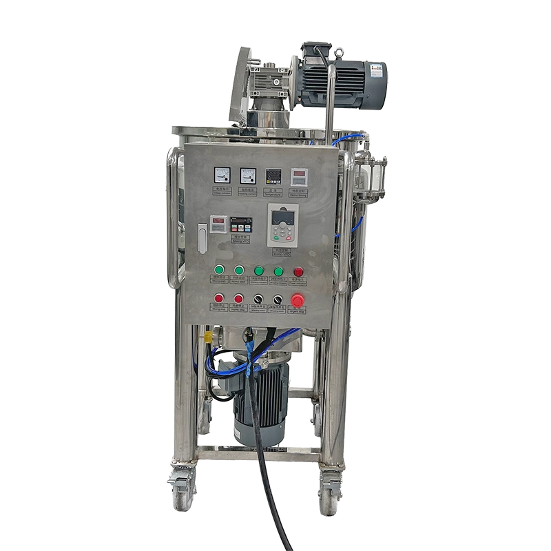
200L Mobile Electric Heating Homogenizing Mixing Tank with High Shear Mixer for Cosmetics, Cream, Lotion, Shampoo and Liquid Products
View Details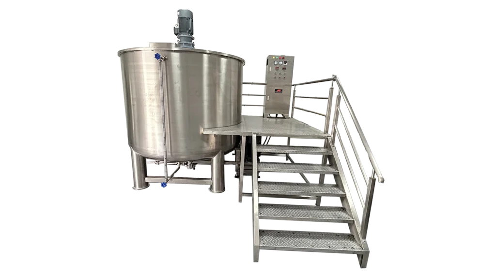
5000L Single Layer Homogenizer Mixing Tank for Liquid Soap, Detergent, Shampoo & Cosmetic Batch Production
View Details
Working Principle
Incoming water first passes through pretreatment selected around the assessed source-water conditions. The multimedia sand filter retains suspended material within its filtration capability. The activated carbon filter provides adsorption treatment, while the softener reduces hardness through its specified ion-exchange process.
Water then passes through the 5 μm cartridge filter before entering the first RO pass. This cartridge is a particulate-filtration component and should not be treated as a sterilizing filter.
High-pressure pumping supplies the driving force for membrane separation. Each RO pass produces a permeate stream and a concentrate stream. In this double-pass configuration, permeate from the first pass becomes feed to the second pass, where it undergoes further membrane treatment.
The approved process drawing determines whether an intermediate tank is used and how the second-pass concentrate is handled. Concentrate recycling, chemical adjustment and automatic flushing must not be assumed without a confirmed flow diagram and operating schedule.
Final permeate enters the specified product-water storage arrangement. Water is released for manufacturing according to the site’s acceptance procedure, with downstream transfer and distribution defined by the production layout.
During operation, personnel follow the supplied control sequence and record the available process readings. Water outside the agreed acceptance limits must be handled through the site’s designated rejection or hold procedure. The push-button control description alone does not establish automatic rejection of off-specification water.
Optional Upgrades & Configurations
| Warranty | 24 Months | Payment Terms | 40% T/T Deposit, 60% Balance Before Shipment (Alibaba Trade Assurance Available) |
| Lead Time | 15–20 Working Days | Packaging | Standard Export Fumigation-Free Wooden Case |
After-Sales & Technical Support
🔧 Common Problems
Possible observable symptoms include reduced final-water output, conductivity readings above the agreed limit, unstable production flow, fluctuating pressure indications or an increasing pressure difference across a filter. Operators may observe weak tank replenishment, an unexpected storage-level change, excessive concentrate discharge or differences between recorded inlet and outlet flows. Pretreatment observations can include cloudy water after a service cycle, visible discoloration, unusual odor or hardness readings outside the specified operating criterion. Mechanical observations may include pump noise, vibration, leakage around connections, water near membrane-housing closures or repeated motor trips. Other observations include inconsistent instrument readings, an incomplete operating sequence, difficulty maintaining the intended valve position or water-quality results outside the site's release limits after storage. These symptoms describe possible operating observations rather than confirmed defects in the supplied equipment.
🛠 Troubleshooting
Problem: Final-water production falls below the agreed operating benchmark. Possible Cause: Feed conditions have changed, a filter is restricted or membrane performance has declined. Recommended Solution: Compare current readings with the commissioning record. Arrange qualified review before changing pressure or recovery settings.Problem: Product-water conductivity exceeds the acceptance limit. Possible Cause: The measurement is unreliable, feed conditions differ or a membrane or sealing issue is present. Recommended Solution: Hold the affected water. Verify the instrument and sampling method before investigating treatment performance.Problem: Pressure difference across the cartridge filter increases. Possible Cause: The cartridge has accumulated retained material or upstream treatment is underperforming. Recommended Solution: Review pretreatment records. Isolate and depressurize the housing before inspection under the service procedure.Problem: The high-pressure pump becomes noisy or vibrates. Possible Cause: Inadequate inlet supply, air entry or a mechanical fault affects operation. Recommended Solution: Stop the affected pump. Obtain qualified inspection before restarting or replacing parts.Problem: Softened-water hardness exceeds the specified criterion. Possible Cause: Regeneration is incomplete, valve routing is incorrect or the resin requires assessment. Recommended Solution: Check the approved service sequence and test method. Follow the softener instructions for corrective work.Problem: Water passes the RO outlet check but fails after storage. Possible Cause: Storage, sampling or downstream handling has affected the result. Recommended Solution: Hold water release. Investigate the complete storage and transfer pathway under the site's quality procedure.
🧼 Cleaning Method
1. Review the approved cleaning instructions for the installed membrane, pretreatment and storage components. 2. Remove the affected water system from production service. 3. Isolate downstream users from the designated cleaning circuit. 4. Shut down the relevant pumping equipment according to its operating procedure. 5. Depressurize the circuit before opening any service connection. 6. Apply the site's lockout procedure before manual access. 7. Configure the approved pretreatment service route. 8. Perform multimedia-filter backwashing according to the supplied filter instructions. 9. Perform activated-carbon servicing according to the approved media procedure. 10. Regenerate the softener according to its component instructions. 11. Replace disposable cartridges through the approved housing-access procedure when required. 12. Configure membrane cleaning equipment only where a compatible cleaning arrangement is supplied or approved. 13. Apply the membrane manufacturer's specified cleaning method when condition assessment requires cleaning. 14. Flush the membrane circuit according to the selected element instructions. 15. Clean storage tanks through their approved access and cleaning arrangement. 16. Sanitize designated components only through a verified material-compatible procedure. 17. Rinse serviced circuits until the specified acceptance criteria are satisfied. 18. Inspect accessible connections before restoring the operating arrangement. 19. Release the water system after the required post-service quality checks.
📋 Maintenance
1. Establish the preventive-maintenance schedule from the installed component documentation. 2. Record available pressure, flow, temperature and conductivity readings against the operating baseline. 3. Review changes in normalized membrane performance where the approved monitoring method provides them. 4. Inspect pretreatment vessels for visible leakage or external deterioration. 5. Assess multimedia-filter service performance using the specified operating checks. 6. Assess activated-carbon condition through the approved monitoring method. 7. Check softener outlet hardness against the specified operating criterion. 8. Inspect the regeneration arrangement according to the softener service instructions. 9. Review cartridge-filter pressure difference before scheduling cartridge service. 10. Inspect pump seals for leakage during routine observation. 11. Service pump bearings according to the installed pump documentation. 12. Examine FRP membrane housings for visible damage through the approved inspection method. 13. Inspect piping supports and accessible connections for deterioration. 14. Check storage-tank fittings according to the approved inspection schedule. 15. Verify measuring instruments through the site's calibration or checking procedure. 16. Test supplied protective functions using the approved functional test method. 17. Arrange electrical inspection by qualified personnel. 18. Inspect caster restraints on the designated mobile assembly. 19. Preserve idle membranes according to the installed element manufacturer's instructions. 20. Record maintenance findings against the equipment and component identification.
⚙️ Installation
1. Review the approved process diagram before preparing the installation area. 2. Verify the delivery route against the complete equipment transport envelope. 3. Obtain approval of the floor and supports for the full operating loads. 4. Inspect delivered assemblies for visible transport damage. 5. Position the equipment using the designated handling method. 6. Secure the mobile assembly at its approved operating location. 7. Position separate tanks according to the final general arrangement. 8. Assemble interconnecting pipework according to the approved process drawing. 9. Connect the source-water supply at the designated inlet. 10. Connect RO concentrate piping to the approved discharge destination. 11. Connect pretreatment service drains according to the drainage schedule. 12. Connect storage-tank fittings according to their assigned duties. 13. Arrange electrical connection by qualified personnel using the final wiring documents. 14. Verify protective earthing before electrical commissioning. 15. Prepare filter media according to the selected supplier instructions. 16. Prepare the softener according to its commissioning procedure. 17. Install cartridges according to the housing manufacturer's instructions. 18. Commission the first RO pass according to the installed membrane documentation. 19. Commission the second RO pass after satisfying the required first-pass preparation conditions. 20. Verify the supplied controls and protective functions. 21. Document water production and quality against the agreed acceptance conditions. 22. Release the installation for production use through the site's approval procedure.
🔩 Spare Parts
Why Choose This Machine
- A defined two-pass treatment route: Processing first-pass permeate through a second RO pass gives buyers a specific configuration to evaluate where a single membrane pass may not meet the required ionic-water specification.
- Broader pretreatment coverage: Multimedia filtration, activated carbon treatment and softening address different feedwater concerns. Their combination supports a structured pretreatment assessment rather than relying on cartridge filtration alone.
- Production buffering: The supplied storage arrangement can separate water-generation timing from batch charging, provided usable tank capacity and downstream delivery are matched to actual demand.
- Clear operating responsibility: Semi-automatic control allows the project to define operator tasks explicitly, including startup, routine observations and any manually initiated service functions.
- Project-specific sourcing: Identifying membrane and electrical selections before ordering helps align replacement availability, documentation and local maintenance preferences.
- Practical line integration: The system provides an identifiable upstream water-preparation section that can be assessed alongside mixing, storage and cleaning requirements during factory planning.
Frequently Asked Questions
Installation Requirements
Assess the floor and supports against the complete operating loads. The listed machine weight is 2000 kg, but its dry or operating basis is not identified. Include water inventory and separate tank loads in the installation assessment. Secure caster-mounted equipment using the approved restraint arrangement.
Provide a source-water supply matched to the final feed specification and required inlet conditions. The listed 0.2–1.5 MPa operating-pressure range must not be used as a universal incoming-water requirement. Confirm the relevant pressure limits separately for each circuit and component.
Provide designated routes for RO concentrate, pretreatment backwash, softener regeneration waste and service drainage. Determine drainage capacity from the approved operating sequences, including any simultaneous discharge.
Match the electrical supply to the ordered voltage, frequency and phase arrangement. Confirm the listed 8 kW power figure against the final electrical schedule. The 110–480 V range describes configuration choices, not an automatically universal input supply.
Define storage connections, downstream transfer duties and sampling access before commissioning. Any compressed-air, cleaning or sanitization services must follow the confirmed equipment scope.
Related Articles


Technical Buyer's Handbook & Deep Insight
Ready to Get a Quote?
Contact our team directly for pricing, customization options, and delivery timelines.
💬 WhatsApp Us NowGet Your Download Link
Please fill in your details and we'll send the download link to your email.