

100L PLC Hydraulic Lift Vacuum Emulsifying Mixer with Diaphragm Discharge Valve for Sanitary Production

The 100L PLC Hydraulic Lift Vacuum Emulsifying Mixer is a sanitary cosmetic cream mixing machine built for labs, OEM contract manufacturers, and pilot-scale skincare producers. It combines vacuum homogenization, automatic hydraulic lid lifting, and a diaphragm discharge valve for clean, repeatable batches of cream, lotion, and gel formulations.
| Total Capacity (L) | 120 | Discharge Method | Electric/Manual Tilting Discharge |
| Working Capacity (L) | 100 | Discharge Valves | Diaphragm Valve |
| Min Batch Size (L) | 30 | Lid Lifting System | Hydraulic Lifting System (Automatic) |
| Structure Type | Triple Layer (with Jacket & Insulation) | Mechanical Seal Brand | Single Mechanical Seal (John Crane/EagleBurgmann Optional) / Double Mechanical Seal (EagleBurgmann) |
| Contact Material | SUS316L Stainless Steel | Tilting System | Electric Tilting |
| Non-contact Material | SUS304 Stainless Steel | Types of Upper Heads | Hydraulic Lifting Head |
| Surface Finish | Interior Mirror Polish (Ra ≤ 0.4 μm) & Exterior Satin/Matte Finish | Top Openings & Accessories | Vacuum Port / Vacuum Feeding Port / Powder Feeding Port / Liquid Inlet / Fragrance Addition Port / Manway / Sight Glass with Wiper / LED Inspection Light / CIP Spray Ball / Vent Filter / Vacuum Gauge / Pressure Sensor / Compressed Air Inlet |
| Jacket Design Pressure (MPa) | 0.3 | Motor Brand | SEW / ABB / Siemens / Top-Tier Chinese Brands (Optional) |
| Main Tank Mixer Type | Uni-directional Anchor Agitator with Central Static Baffles | vem_electrical_components | Schneider / ABB / Siemens / Omron / Fuji /Mitsubishi(Optional/Customizable) |
| Mixing Speed (rpm) | 0–63 rpm | Oil & Water Pot | Standalone Main Unit Only |
| Mixing Motor Power (kW) | 1.5 | Fully Raised Height (mm) | 2780 |
| Frequency Control | Variable Speed with VFD (Delta, Siemens, ABB, Schneider, Optional) | Explosion Proof | Standard Non-Explosion Proof (For Regular Cosmetics) |
| Scraper System | Wall-Scraping PTFE Scrapers | Platform & Ladder | Bench-top / Compact Frame (No Platform) |
| Homogenizer Position | Bottom-entry Homogenizer | Voltage | Configurable to local grid (110V–480V, 50/60Hz, Single or 3-Phase) |
| Homogenizer Type | High Shear Stator-Rotor Homogenizer | Total Power (kW) | 6 |
| Homogenizer Power (kW) | 4 | Drive Type | Electric |
| Homogenizer Speed (rpm) | 0–3000 rpm (Variable Speed) | Installation Type | Floor-Standing |
| Max Processing Viscosity (mPa·s / cP) | 30,000 | Automation Level | Fully Automatic |
| Heating Method | Electric Heating via Jacket / External Steam Heating (Optional) | Control System | PLC + HMI Touch Screen Control |
| Cooling System | Tap Water / Cooling Tower Circulation (Chilled Water / Glycol Circulation Optional) | PLC System | Siemens |
| Water Chiller | External Water Chiller Unit (Optional) | HMI / Touch Screen | Siemens |
| Temperature Control Accuracy | ±1°C | Control & Interaction Systems | Fully Automated (High-Tech / Industry 4.0) |
| Vacuum Degree (MPa) | -0.09 | Machine Dimensions(L*W*H)mm | 2000mm*820mm*1980mm |
| Vacuum Pump Brand | High-quality domestic/joint venture brands | Machine Weight (kg) | 600 |
Product Gallery






Product Video
Product Overview
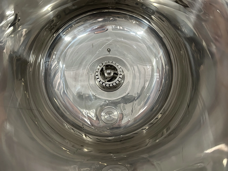
This machine provides a total vessel capacity of 120L with a recommended working capacity of 100L and a minimum practical batch size of 30L — a range that covers most pilot runs and small commercial batches without wasting formulation on partial fills. The vessel is a triple-layer jacketed design with SUS316L mirror-polished contact surfaces (Ra ≤ 0.4 μm) and a SUS304 outer frame.
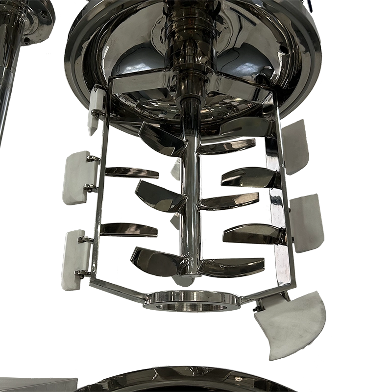
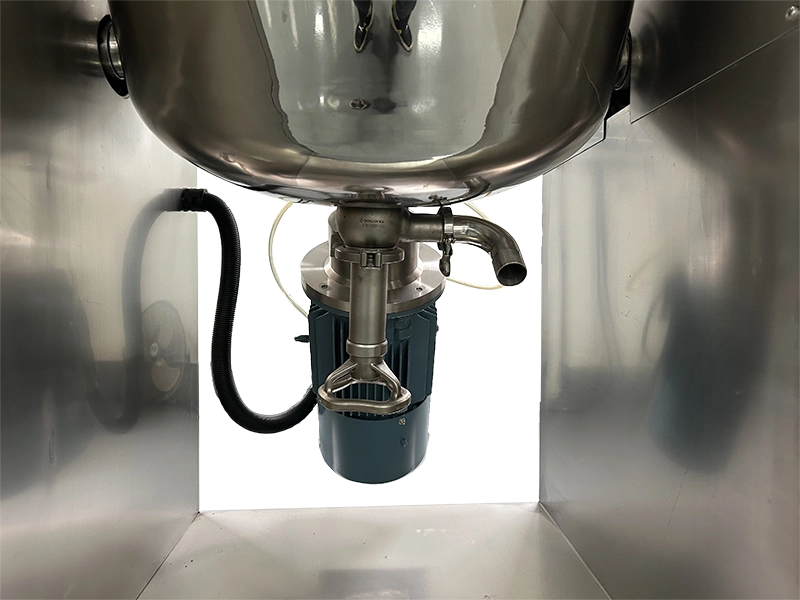
Mixing is handled by two separate systems working together. A uni-directional anchor agitator with PTFE wall scrapers keeps material moving along the vessel wall at up to 63 rpm, while a bottom-entry, high-shear rotor-stator homogenizer runs up to 3000 rpm for fine particle reduction in viscosities up to 30,000 mPa·s. During processing, the vacuum system pulls down to -0.09 MPa to remove trapped air, which improves finished texture and reduces oxidation risk for sensitive actives.
The lid raises and lowers automatically through a hydraulic lifting system, and the whole vessel tilts electrically for discharge through a sanitary diaphragm valve — a detail that matters more than it sounds, since diaphragm valves leave far less residual product behind compared to ball or butterfly valves, which shortens cleaning cycles and reduces cross-batch contamination risk. Temperature is held to ±1°C through jacket heating (electric standard, steam optional) and water or chiller cooling.
Everything runs through a Siemens PLC and HMI touchscreen, supporting recipe storage and repeatable batch sequencing for manufacturers who need the same result every time, not just this time.
Machine Configuration
The 100L unit is built from five functional modules rather than one fixed block. The vessel module is the triple-layer jacketed tank (120L total, 100L working), insulated to reduce heat loss during long mixing cycles. The mixing module pairs a 1.5kW anchor agitator with PTFE scrapers against a 4kW bottom-entry rotor-stator homogenizer — two different mixing actions covering both bulk circulation and fine emulsification.
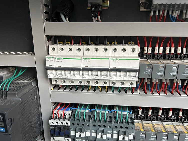
The lifting and discharge module includes the hydraulic lid lift, electric tilting frame, and the diaphragm discharge valve at the base. The process control module covers the vacuum port, powder and liquid feeding ports, fragrance addition port, sight glass with wiper, LED inspection light, and CIP spray ball — the parts operators interact with most during a working batch. Finally, the automation module is the Siemens PLC and HMI, wired through Schneider, Siemens, or Omron electrical components depending on customer preference, housed in a floor-standing frame roughly 2 meters long.
Key Features
Bottom-entry rotor-stator homogenizer for fine, stable emulsions
Mirror-polished SUS316L interior for pharma-grade hygiene
Vacuum degassing to -0.09 MPa cuts air bubbles and oxidation
Hydraulic lid lift removes manual lifting between batches
Diaphragm discharge valve leaves minimal product residue
Siemens PLC stores recipes for repeatable batch results
Jacket heating/cooling holds ±1°C across the full batch
Electric tilting discharge reduces manual handling risk
CIP spray ball shortens cleaning time between formulations
Compact floor footprint suits labs and pilot production rooms
Applications
- Cosmetic Cream & Lotion, and Skin Care
- Detergents, Liquid Washing & Household Cleaning
- Pharmaceutical & Ointment Products
- Sauce, Condiment & Food Paste
- Toothpaste & Oral Care Products
Recommended Machines


Working Principle
The machine follows a clear Machine → Input → Process → Output sequence, which keeps every batch traceable through the HMI log.
Materials go in first. Oil phase, water phase, actives, and powders enter through the vacuum feeding port, liquid inlet, or powder feeding port, and operators can confirm loading visually through the sight glass under the LED inspection light.
Heating and circulation happen next. The jacket brings the batch to formulation temperature while the anchor agitator scrapes the vessel wall continuously, so nothing sits still long enough to scorch or separate — this matters more than people expect with thicker cream bases.
Homogenization follows once temperature is stable. The bottom-entry rotor-stator head engages at up to 3000 rpm, breaking down oil droplets and reducing particle size. Most formulators run this stage under vacuum simultaneously, since pulling air out while shearing the product gives a smoother, more stable emulsion than running the two steps separately.
Vacuum degassing continues through the cycle, holding down to -0.09 MPa to clear trapped air and reduce foam — a step that becomes more noticeable in the finished product’s texture than in the process itself.
Discharge closes the loop. Once the batch meets the programmed parameters, the frame tilts electrically and the diaphragm valve opens for a clean, low-residue transfer to filling equipment or a holding tank, with the full cycle — temperatures, speeds, timing — recorded on the HMI for quality records.
Optional Upgrades & Configurations
| Warranty | 24 Months | Payment Terms | 40% T/T Deposit, 60% Balance Before Shipment (Alibaba Trade Assurance Available) |
| Lead Time | 15–20 Working Days | Packaging | Standard Export Fumigation-Free Wooden Case |
Recommended Accessories


After-Sales & Technical Support
🔧 Common Problems
Operators of this machine most commonly run into a handful of recurring issues that are worth knowing before they come up on the floor. Vacuum failing to reach the target -0.09 MPa is usually a worn lid gasket, a loose sight glass seal, or a vent filter overdue for replacement, not a pump problem. Temperature drifting outside ±1°C often traces back to reduced jacket water flow or scale buildup on the heat exchange surface, especially in areas with hard water. Uneven texture or visible streaking in the finished emulsion frequently comes from running the homogenizer at too low a speed for the formulation's viscosity, or from adding powders too fast before the liquid phase is properly pre-mixed. Mechanical seal leakage, particularly on single-seal configurations, tends to show up after extended high-vacuum runs, which is a common reason buyers move to a double mechanical seal on their next order. A sticking discharge valve is almost always a cleaning residue issue rather than a hardware fault, and usually clears up with a more thorough CIP cycle and a quick diaphragm inspection.
🛠 Troubleshooting
Problem: Vacuum pump won't reach -0.09 MPa Possible Cause: Worn lid gasket, loose sight glass fitting, or clogged vent filter Recommended Solution: Inspect and replace gaskets, tighten sight glass fittings, and clean or replace the vent filterProblem: Batch temperature drifts outside ±1°C Possible Cause: Reduced jacket water flow or scale buildup on heat exchange surfaces Recommended Solution: Check water flow rate, descale the jacket, and recalibrate the temperature sensorProblem: Emulsion texture is uneven or shows streaking Possible Cause: Homogenizer speed too low for the batch viscosity, or powder added before liquids were pre-mixed Recommended Solution: Increase homogenizer speed within the 0–3000 rpm range and confirm liquid-before-powder loading orderProblem: Mechanical seal shows fluid leakage Possible Cause: Normal seal wear from extended high-vacuum cycles Recommended Solution: Replace the seal, and consider a double mechanical seal upgrade for high-frequency productionProblem: Diaphragm discharge valve is stiff or won't seal properly Possible Cause: Product residue buildup on the valve seat Recommended Solution: Run a targeted CIP cycle on the discharge valve and inspect the diaphragm membrane for wearProblem: Agitator motor trips or runs hot Possible Cause: Batch viscosity above the rated limit, or scraper blades obstructed by buildup Recommended Solution: Confirm batch viscosity stays within 30,000 mPa·s and check PTFE scrapers for damage or residue
🧼 Cleaning Method
1. Fully discharge the batch through the diaphragm valve using the electric tilting function before beginning any rinse. 2. Close the discharge valve and introduce cleaning solution, typically warm softened or purified water, through the liquid inlet or manway. 3. Run the CIP spray ball to circulate cleaning solution across the vessel walls, lid underside, and agitator surfaces for the programmed cycle time. 4. Run the agitator and homogenizer briefly at low speed during the rinse to clean residue off the blades and rotor-stator head. 5. Drain the first rinse through the diaphragm valve and check the discharge for remaining residue or discoloration. 6. Repeat the CIP cycle with fresh water until the discharge runs clear, usually two to three cycles depending on the prior formulation. 7. Where required, run a final sanitizing rinse with an approved sanitizing agent through the same CIP spray ball system. 8. Raise the lid via the hydraulic lifting system and visually check the interior surface, sight glass, and gaskets for any remaining residue. 9. Wipe down external surfaces, the sight glass wiper, and the LED inspection light housing with a clean, lint-free cloth. 10. Leave the lid open or partially raised between batches so the vessel dries fully before the next formula goes in.
📋 Maintenance
1. Check mechanical seals weekly for leakage or unusual wear, particularly after high-vacuum production runs. 2. Inspect jacket water lines monthly for scale buildup, leaks, or reduced flow that could affect heating and cooling performance. 3. Lubricate hydraulic lifting components on the manufacturer's recommended schedule to keep lid movement smooth. 4. Examine PTFE wall-scraping blades every one to two months for wear or loss of contact with the vessel wall, replacing as needed. 5. Test vacuum performance periodically, and replace vent filters if the system struggles to reach -0.09 MPa. 6. Listen for unusual noise from the homogenizer bearing during operation and schedule inspection per the motor manufacturer's guidance. 7. Calibrate temperature and pressure sensors quarterly to keep the rated ±1°C accuracy and reliable PLC readings. 8. Inspect the diaphragm discharge valve regularly for wear or residue buildup that could compromise the seal, especially under frequent production. 9. Check electrical cabinet components for dust accumulation or loose connections during scheduled downtime. 10. Keep a maintenance log of every inspection, part replacement, and calibration date to support GMP documentation and warranty claims.
⚙️ Installation
1. Confirm the site has adequate floor space for the machine footprint and clearance for the fully raised lid height of 2780mm. 2. Verify the floor supports the machine's operating weight of roughly 600kg and is level to prevent vibration during mixing. 3. Connect electrical supply per the configured voltage, ensuring proper grounding for the PLC and HMI panel. 4. Connect water lines for jacket heating/cooling and CIP rinsing, confirming tap pressure falls within 0.2–0.4 MPa. 5. If steam heating was selected, connect the steam supply and condensate return piping accordingly. 6. Connect compressed air to the designated inlet, confirming pressure and dryness meet the pneumatic component specifications. 7. Test the vacuum system, confirming the pump reaches -0.09 MPa without leaks at gaskets or fittings. 8. Power on the PLC and HMI, load initial recipe parameters, and run a dry cycle without product to confirm agitator, homogenizer, lift, and tilt functions. 9. Run a water-based test batch to verify heating, cooling, vacuum, and discharge before processing an actual formulation. 10. Record baseline readings — temperature accuracy, vacuum level, cycle time — for future maintenance comparison and operator training.
🔩 Spare Parts
Why Choose This Machine
SUS316L construction built to hold up under repeated GMP-level cleaning
Working capacity matched to real pilot and small-batch production needs
Handles thick, difficult formulations up to 30,000 mPa·s without stalling
Hydraulic lifting removes a physically demanding step from daily operation
Choice of electric or steam heating depending on facility utilities
Diaphragm valve and CIP spray ball shorten changeover time between SKUs
Siemens PLC gives consistent results across operators and shifts
Motor, seal, and electrical brands can be configured to match existing plant standards
Our engineering team strives to match each machine’s configuration to the buyer’s actual formulation range, not just a spec sheet
Spare parts and after-sales support available for long-term operation
Downloads
Frequently Asked Questions
Installation Requirements
Water supply for jacket cooling and CIP rinsing should run at roughly 0.2–0.4 MPa tap pressure, with a floor drain nearby for wastewater. Softened or purified water is preferable for CIP cycles to avoid mineral scale on the mirror-polished interior over time. Electrical supply must match the configured voltage (110V–480V, single or three-phase) on a dedicated circuit sized for the 6kW total draw, with proper grounding for the PLC cabinet.
If steam heating is selected instead of the standard electric jacket, a steam generator with filtered supply and condensate return piping is required — this is a common point buyers overlook when comparing electric vs. steam options at order time. Compressed air, typically 0.4–0.6 MPa from a clean, dry source, supports the pneumatic components and compressed air inlet port. If chilled water cooling is preferred over standard tap water, an external chiller unit should be positioned within reasonable line distance of the jacket connections.
Related Articles


Technical Buyer's Handbook & Deep Insight
Ready to Get a Quote?
Contact our team directly for pricing, customization options, and delivery timelines.
💬 WhatsApp Us NowGet Your Download Link
Please fill in your details and we'll send the download link to your email.