Designing a cooling water system for a vacuum emulsifying machine is easy to underestimate.
At first glance, the job seems straightforward: connect a water tank to the mixer jacket, install a pump, and circulate the water until the product reaches the required temperature. In practice, that approach can lead to longer cooling cycles, unstable production temperatures, unnecessary water consumption, oversized pumps, or a chiller that costs far more to operate than the factory actually needs.
The scope here is jacket cooling of the product. Mechanical seal cooling and water-ring vacuum-pump service water have separate requirements and must not be sized from this jacket example. A mechanical seal failure case illustrates why auxiliary cooling connections also need their own checks.
The better approach is to start with the process rather than the equipment.
How much heat must be removed from the product? How many batches will the factory run each day? How long is each cooling cycle? How much time is available between batches? What is the ambient temperature? Can the cooling water naturally release enough heat overnight? Does the factory need continuous cooling, or is production intermittent?
These questions matter because a cooling water system for a 1,000 kg vacuum emulsifying machine operating four batches per day has very different requirements from a continuously running production line.
This article uses a worked engineering example: a 1,000 kg batch cooled from 100°C to 50°C in approximately 60 minutes, with cooling starting every two hours and four batches per day. The values are design assumptions, not a record of verified site performance. Confirm the actual formulation, temperature, vessel pressure and any evaporation before using this sensible-heat calculation for a real process.
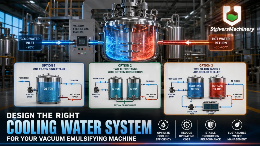
The main systems compared are:
- One 20-ton cooling water storage tank
- Two 10-ton cooling water tanks with a bottom equalizing connection
- Two independent 10-ton tanks with an air-cooled chiller
- Two 10-ton tanks with an optional auxiliary chiller for high-temperature environments
The goal is not to claim that one configuration is universally superior. Instead, the objective is to show how to design a recirculating cooling water system around the actual production schedule, thermal load, climate, and operating requirements.
For intermittent production, one or two storage tanks may provide useful thermal buffering. A dual-tank arrangement is a candidate, not a proven preference: compare usable water volume, hydraulic behavior, heat rejection and total cost before selecting it.
In hotter climates or higher-throughput plants, however, active heat removal may become necessary.
The key is to determine when.
Worked Engineering Example: 1000kg Vacuum Emulsifying Machine Setup
Consider a factory producing cosmetics, personal care products, creams, lotions, or other high-viscosity formulations using a vacuum emulsifying mixer.
The production requirement is:
- Product batch size: 1,000 kg
- Initial product temperature: 100°C
- Target product temperature: 50°C
- Cooling time: approximately 60 minutes
- Cooling cycle: approximately once every two hours
- Production: four batches per day
- Initial cooling water temperature: approximately 20°C
- Ambient temperature: dependent on location and season
The factory wants to reuse cooling water rather than discharge and replace it after every production batch.
That is a sensible approach.
A recirculating cooling water system can significantly reduce freshwater consumption while making the cooling process easier to control. It also gives the plant a more practical way to manage the thermal energy generated during production.
However, once cooling water is reused, the engineering question changes.
The problem is no longer simply:
“How much water do we need?”
The more important question becomes:
“How much heat can the water absorb, and how quickly can the system remove that heat before the next production cycle?”
This distinction is critical.
A single tank and a pair of tanks have the same sensible-heat storage capacity only when their actual water mass and usable temperature range are equal. Nominal tank capacity is not working water volume: freeboard and minimum operating levels reduce the usable inventory. Different inlet, outlet and control arrangements can affect the supply temperature, but dividing a tank does not create additional thermal capacity.
For StriversMachinery, this is an important consideration when designing complete equipment solutions for cosmetic, chemical, food, pharmaceutical, and personal care production lines.
The objective should not be to sell the largest tank or the largest chiller.
The objective should be to strive for the simplest cooling system that can reliably meet the production requirement.
Production Schedule and Cooling Window
The production schedule is one of the most important variables in cooling system design.
Suppose the factory runs four 1,000 kg batches per day.
If each cooling cycle lasts approximately 60 minutes and the batches are spaced two hours apart, the cooling load is intermittent rather than continuous.
A simplified operating pattern might look like this:
Batch 1
↓
Cooling: 60 min
↓
Production / Waiting
↓
Batch 2
↓
Cooling: 60 min
↓
Production / Waiting
↓
Batch 3
↓
Cooling: 60 min
↓
Production / Waiting
↓
Batch 4
↓
Cooling: 60 min
↓
Overnight Shutdown
The important point is that the system is not necessarily removing the full cooling load 24 hours per day.
The factory has:
- Cooling periods
- Gaps between batches
- Production intervals
- Overnight shutdown periods
Idle periods provide time for heat rejection, but they do not establish the rate of heat removal. A complete design needs a daily heat balance and supply-temperature profile across consecutive production days.
This is why the same 1,000 kg vacuum emulsifying machine may require different cooling water equipment in different factories.
A plant running four batches per day in a mild climate might use thermal buffering with ambient heat rejection, provided calculation or representative measurements show that the supply-temperature limits and recovery requirement are met.
A plant running 12 or 20 batches per day may need active refrigeration.
A plant in a tropical environment may also need a chiller even at a lower production rate if the cooling water cannot return to an acceptable temperature between production cycles.
The production schedule therefore needs to be considered before selecting the tank capacity or chiller size.
The Role of the 10-Ton Cooling Water Tank
A 10-ton tank contains approximately 10,000 kg of water.
The thermal capacity of that water is significant.
Water has a specific heat capacity of approximately:
4.186 kJ/kg·K
Therefore, a 10,000 kg water tank can absorb a substantial amount of thermal energy for every degree Celsius that its temperature increases.
This gives the tank a second function beyond simple water storage.
It acts as a thermal buffer.
Instead of forcing the refrigeration system to remove all heat immediately at the exact moment the product is being cooled, the tank can temporarily absorb and store some of the thermal energy.
This concept becomes particularly useful for intermittent production.
The factory can store cooling water, receive warmer return water and remove heat during production gaps or overnight. Storage delays the need to reject heat; it does not eliminate that heat. Natural loss from a bare tank, a dry cooler, a suitable heat exchanger and a chiller provide different heat-rejection arrangements.
For this example, four batches add about 211 kWh of product sensible heat each day. If all of that heat were stored and then rejected during a 15-hour shutdown, the required average overnight rejection would be about 14.1 kW. Heat already rejected during production reduces that overnight duty; vessel, piping and pump contributions may add to the overall load. These terms must be evaluated on one consistent basis.
Evaluate ambient heat loss from exposed surface area, insulation, water and air temperatures, airflow and other relevant conditions; where applicable, include evaporation separately. A tank cooling curve or a suitable heat-transfer model is needed. A mild climate and a long shutdown alone do not demonstrate that either tank arrangement can return to 20°C.
That is where the comparison between one 20-ton tank and two 10-ton tanks becomes more interesting.
Thermal Load and Cooling Capacity Calculations
Before comparing tank configurations, it is necessary to estimate the thermal load.
A basic cooling load calculation can be expressed as:
Q = m × Cp × ΔT
Where:
- Q = thermal energy that must be removed
- m = product mass
- Cp = specific heat capacity of the product
- ΔT = temperature reduction
For this example:
- m = 1,000 kg
- Cp = approximately 3.8 kJ/kg·K as a simplified engineering assumption
- ΔT = 100°C − 50°C = 50°C
Therefore:
Q = 1,000 × 3.8 × 50
Q = 190,000 kJ
Converting this into kilowatt-hours:
190,000 ÷ 3,600 ≈ 52.8 kWh
The theoretical heat removal requirement is therefore approximately:
52.8 kWh of thermal energy per batch
For four batches per day:
52.8 × 4 = 211.2 kWh of thermal energy per day
This figure is useful for understanding the overall heat balance.
However, it should not be interpreted as a direct electricity consumption figure.
The 211.2 kWh represents the approximate amount of thermal energy that must be removed from the product.
A refrigeration system uses electricity to remove heat.
The electrical consumption depends on:
- Chiller COP
- Condensing temperature
- Ambient temperature
- Chilled water temperature
- Part-load efficiency
- Pump power
- Fan power
- Operating hours
A natural cooling system, by contrast, may remove heat using ambient air and time without requiring compressor electricity.
This is one reason why thermal load and electrical energy consumption should not be treated as the same thing.
Why the Theoretical 52.8kW Load Is Not Automatically a 52.8kW Chiller
If 52.8 kWh of thermal energy must be removed during a 60-minute cooling cycle, the theoretical average cooling load is approximately:
52.8 kW
This does not automatically mean that the factory must purchase a 52.8 kW chiller.
The actual cooling system must account for the heat transfer process.
The product does not transfer heat directly into the chiller.
The heat normally travels through several stages:
Product → Product-side heat transfer → Vessel wall separating product from jacket water → Cooling water → Storage / heat-rejection circuit → Suitable heat exchanger or chiller, if fitted → Heat sink
Every stage introduces some resistance.
The actual cooling performance depends on:
- Product viscosity
- Product circulation
- Agitation speed
- Jacket design
- Heat transfer area
- Cooling water flow rate
- Water temperature
- Pipe diameter
- Pump pressure
- Ambient temperature
Verify both the heat duty and the rate at which the vessel can transfer it. Include relevant vessel metal, agitation input, residual heating, fouling and other loads, then assess uncertainty and equipment derating. A blanket 20–30% addition cannot replace these checks. If jacket area or product-side heat transfer limits cooling, a larger chiller alone may not meet the 60-minute target.
The final equipment selection should also consider high ambient temperatures.
An air-cooled chiller rated at a particular capacity under standard test conditions may deliver a lower effective capacity when the outdoor temperature rises significantly.
This is particularly important in hot climates.
A system designed for a mild 20°C ambient environment may not perform the same way during a 35°C summer afternoon.
Product Specific Heat Matters
The calculation above assumes a product specific heat capacity of approximately 3.8 kJ/kg·K.
That is a useful engineering assumption for preliminary analysis, but it should not be treated as a universal value.
Different products behave differently.
A water-rich lotion, a high-oil cream, a petroleum-based ointment, a toothpaste, and a highly concentrated cosmetic formulation can all have different thermal properties.
The actual Cp value may vary depending on:
- Water content
- Oil phase
- Solid content
- Product composition
- Temperature
- Concentration
Therefore, a preliminary cooling load calculation should be treated as an engineering estimate.
For a final design, StriversMachinery would normally need to confirm the product formulation or obtain reliable thermal data from the customer.
This is particularly important when the customer requires a strict cooling time, such as:
“The product must cool from 100°C to 50°C within 60 minutes.”
The more demanding the cooling target, the more important accurate product data becomes.
Cooling Water Flow Rate Calculation
The required cooling water flow rate can be estimated using:
Qdot = mdot × Cp × ΔTwater
For the water-side heat-transfer rate, use power rather than total batch energy. The required mass flow is:
mdot = Qdot ÷ (Cp × ΔTwater)
Where:
- mdot = cooling water mass flow rate, kg/s
- Qdot = heat-transfer rate, kW or kJ/s
- Cp = water specific heat, approximately 4.186 kJ/kg·K
- ΔTwater = water temperature rise through the jacket, K or °C
For example, if the system is designed around a cooling load of approximately 53 kW and the cooling water is allowed to rise by 5°C through the jacket, the required water flow is approximately:
53 ÷ (4.186 × 5)
≈ 2.53 kg/s
This is approximately:
9.1 m³/h
At 9.1 m³/h, about 9.1 m³ cumulatively passes through the jacket during one hour. This circulation total is not the size of a separate water parcel or the required tank volume. The instantaneous flow and temperature rise can vary over a batch; verify jacket performance and flow limits rather than treating this average as a pump specification.
This simplified calculation illustrates an important point:
The cooling water flow requirement is not determined simply by the size of the emulsifying machine.
A 1,000 kg vacuum emulsifying mixer may require a different flow rate depending on:
- Jacket area
- Jacket pressure
- Heat transfer coefficient
- Product viscosity
- Cooling water temperature
- Desired cooling time
The final pump selection therefore needs to be based on the actual hydraulic and thermal requirements of the equipment.
Peak Cooling Load vs. Thermal Buffering
This is one of the most important concepts in the entire system design.
The calculated product load is about 52.8 kW averaged over one hour. The actual initial and later heat-transfer rates must be established from the cooling curve; a peak of 50–70 kW has not been demonstrated by this calculation.
But that does not necessarily mean the refrigeration system must continuously provide the entire peak capacity throughout the day.
Thermal buffering may reduce the required refrigeration peak when the working temperature range, usable storage and recovery schedule permit it. It does not reduce the total heat that ultimately needs to leave the system.
Consider the difference between these two approaches.
Direct Refrigeration
Product
↓
Mixer Jacket
↓
Chilled Water
↓
Chiller
↓
Heat Rejection
Without meaningful storage, the selected heat-removal equipment must accommodate the time-varying duty. Approximately 52.8 kW is the calculated one-hour average, not a measured instantaneous peak.
Thermal Buffering
Product
↓
Mixer Jacket
↓
Cold Water Tank
↓
Hot Water Tank
↓
Natural Cooling or Chiller
The storage tanks temporarily absorb and redistribute the thermal load.
This is similar to using a battery.
The tank does not eliminate heat.
It gives the system more flexibility in deciding when and how that heat is removed.
For intermittent production, that can be a major advantage.
The factory may use a relatively large volume of water as a thermal buffer during the one-hour cooling cycle, then remove the accumulated heat during the following production interval or overnight.
This is why it is often a mistake to select a chiller solely from the peak theoretical cooling load without first considering the production schedule.
A factory should strive to match the refrigeration system to the actual heat balance.
How a Recirculating Cooling Water System Works
A practical recirculating cooling water system for a vacuum emulsifying machine can be divided into two functional circuits.
The first circuit delivers cooling water to the emulsifying machine.
The second circuit removes accumulated heat from the cooling water.
Keeping these two functions clear makes the entire system easier to understand.
A simplified configuration is:
Cold Water Tank
      ↓
Automatic Booster Pump
      ↓
Vacuum Emulsifying Machine Jacket
      ↓
Hot Return Water
      ↓
Hot Water Tank
      ↓
Circulation Pump
      ↓
Air-Cooled Chiller
      ↓
Cold Water Tank
The system therefore consists of:
- Cold water storage
- Hot water storage
- Automatic water supply
- Product-side heat transfer
- Heat removal
- Temperature monitoring
- Level control
- Safety protection
Pump 1: Automatic Booster Pump
The first pump is the automatic booster pump.
Its job is to take water from the cooling water storage tank and deliver it to the vacuum emulsifying machine jacket.
This pump should not be confused with the circulation pump used in the chiller loop.
The booster pump is primarily concerned with supplying the emulsifying machine with the required pressure and flow.
The desired operating logic is typically:
Cooling demand from machine / PLC or a suitably designed pressure-control system → Check permitted levels and equipment readiness → Start supply pump and establish the approved valve path → Prove jacket flow → Complete cooling → Stop or modulate pump and valves in the approved sequence
This type of arrangement is useful because the pump does not need to run continuously when the emulsifying machine is not cooling.
Depending on the system design, automatic operation can be controlled through:
A cooling-demand signal, suitable pressure sensing and approved valve sequencing may start the pump. Flow switches normally prove established flow; a zero-flow switch alone may not provide a workable start signal. VFD control, bypass arrangements and pump stop logic must suit the actual system.
The final control strategy should be matched to the customer’s automation system.
A suitably designed pressure-controlled supply pump may work for a simple installation. Check stop/start cycling, deadheading, minimum flow, shutoff head and the jacket pressure rating; a generic domestic booster arrangement is not automatically suitable.
For a more sophisticated production line, the pump can be integrated with the machine PLC so that cooling demand automatically starts and stops the pump.
The system should also include low-water protection.
A pump should never be allowed to run dry.
A low-level sensor in the tank can provide a shutdown signal if the water level falls below the safe operating point.
Pump 2: Chiller Circulation Pump
The chiller circuit needs its specified flow, but that does not always require purchasing a separate external pump.
The circulation pump moves water through the heat-removal circuit:
Hot Water Tank
↓
Circulation Pump
↓
Air-Cooled Chiller
↓
Cold Water Tank
This pump is responsible for maintaining the required water flow through the chiller.
Its operation is therefore closely linked to the chiller’s evaporator requirements.
The chiller manufacturer may specify:
- Minimum flow
- Nominal flow
- Maximum flow
- Required pressure
- Allowable pressure drop
Use the chiller’s integrated pump if it provides the required flow and head, or select an external circulation pump where the design requires one. Preserve minimum evaporator flow and the manufacturer’s startup and shutdown sequence.
If the flow through the chiller is too low, the system may experience poor heat transfer or trigger a low-flow protection alarm.
If the pump is significantly oversized, the system may consume unnecessary energy and create excessive pressure or flow through the heat exchanger.
The pump should therefore be selected from actual hydraulic calculations rather than simply choosing the largest available model.
The Two-Pump Concept
The difference between these two pumps is fundamental.
The automatic booster pump supplies the machine.
The circulation pump manages the chiller loop.
Separating the process-supply duty from the heat-rejection duty can simplify control in the illustrated arrangement. Two external pumps are not a universal requirement; other approved hydraulic layouts may perform both functions differently.
This makes troubleshooting easier and allows each pump to operate according to its own control logic.
The chiller loop may continue after product cooling stops only when tank levels, available transfer volume and equipment flow limits permit it. In an independent two-tank arrangement, continued transfer from the hot tank to the cold tank can otherwise empty one tank or overflow the other.
This separation gives the system more flexibility.
Cooling Water Storage Tank Installation: Indoor vs. Outdoor
The location of the cooling water tank can affect both system performance and maintenance.
The decision should be made during factory layout planning rather than after the equipment has already been purchased.
Indoor Installation
Indoor installation has several advantages.
The biggest is temperature stability.
An indoor tank is protected from:
- Direct sunlight
- Rain
- Wind
- Extreme outdoor temperature swings
Indoor placement may make ambient conditions more stable, but natural heat rejection still needs verification. Heat released into the room also becomes a ventilation or building-cooling load.
Indoor installation can also shorten the distance between the storage tank and the emulsifying machine.
A shorter pipe run may reduce:
- Pressure loss
- Pump head requirements
- Pipe installation cost
Maintenance is usually easier as well.
Recommended Equipment

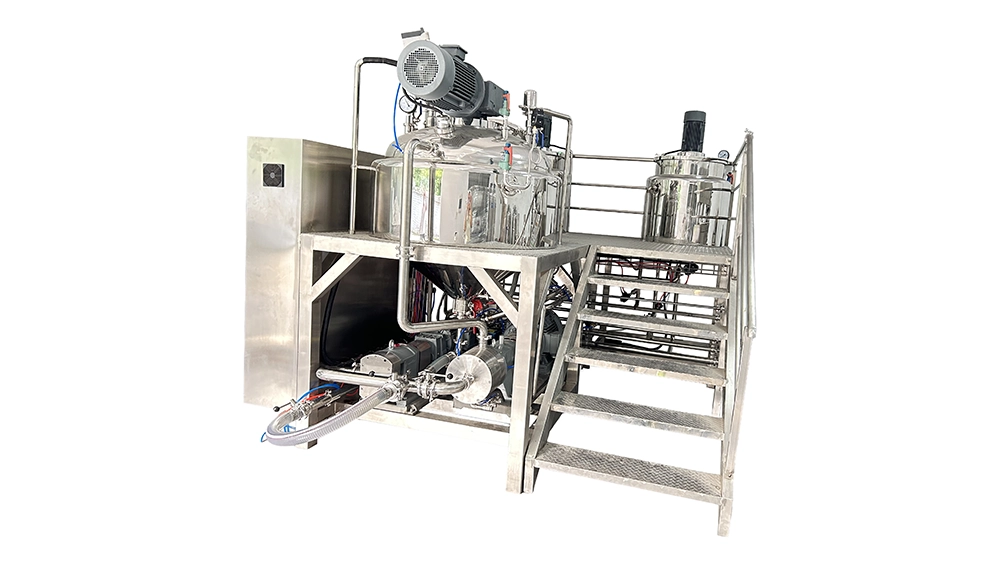
100 LITERS Hydraulic Lift Vacuum Emulsifying Machine for Cream, Lotion & Cosmetic Production
View Details

Technicians can inspect the tank and piping without working in direct sun or bad weather.
However, indoor installation requires attention to:
- Floor loading
- Available space
- Maintenance clearance
- Condensation
- Ventilation
- Drainage considerations
A 10-ton water tank contains approximately 10,000 kg of water.
Two tanks contain approximately 20,000 kg of water.
The structural capacity of the floor must therefore be evaluated before installation.
The tank itself also adds weight.
For a stainless steel tank, the total operating load is higher than the water weight alone.
A factory should confirm that the floor can safely support the combined weight of:
- Water
- Tank
- Insulation
- Piping
- Accessories
Outdoor Installation
Outdoor installation can free valuable factory floor space.
It may also simplify the placement of an air-cooled chiller because the chiller itself generally requires access to ambient air for heat rejection.
However, outdoor tanks face additional challenges.
These include:
- Solar radiation
- Rain
- UV exposure
- Seasonal temperature changes
- Cold weather
- Wind
- Contamination
If the tank is intended to support natural cooling, the outdoor environment can either help or hurt.
A cool outdoor night may accelerate heat dissipation.
A hot summer afternoon with direct sunlight may do the opposite.
Therefore, outdoor installation should not automatically be assumed to improve natural cooling.
The tank should be properly insulated when stable water temperatures are required.
Outdoor insulation should also be protected against:
- UV radiation
- Rain
- Mechanical damage
The final installation should be designed around the local climate.
Indoor Tank Drainage Considerations
Evaluate drainage, containment and overflow arrangements against the site design, credible release volume and applicable local requirements; do not infer an exemption or a universal requirement from tank size alone.
However, drainage should be evaluated as part of the engineering design.
The main reason is simple:
Ten tons of water is a lot of water.
Two tanks represent approximately 20 tons of stored water.
If a major leak occurs, the consequences can be serious.
Drainage considerations should therefore account for several possible situations:
- Tank leakage
- Pipe leakage
- Overflow
- Tank cleaning
- Maintenance
- Emergency draining
- Condensation from cold surfaces
Depending on the facility, possible solutions include:
- Floor drains
- Drainage channels
- Collection pits
- Emergency drainage
- Leak detection
The right solution depends on the factory’s building design and local requirements.
The goal is not necessarily to build an elaborate drainage system.
The goal is to prevent an unexpected water release from damaging:
- Electrical equipment
- Production machinery
- Finished products
- Flooring
- Building structures
A properly planned installation should strive to manage water safely before a problem occurs.
Storage Tank Material Selection
Select materials for this utility-water circuit from water chemistry, treatment chemicals, temperature, corrosion risk and maintenance requirements. A cosmetic product application does not automatically make the cooling water a product-contact or purified-water service.
The best material for a cosmetic production line is not necessarily the best material for a general industrial cooling system.
SUS304 Stainless Steel
SUS304 is commonly used for general industrial water storage.
It offers:
- Good corrosion resistance
- Good mechanical strength
- Easy fabrication
- Reasonable cost
For standard cooling water applications, SUS304 can be an economical choice.
SUS316L Stainless Steel
SUS316L may be appropriate where the assessed corrosion conditions justify it; it is not mandatory merely because the cooling loop serves cosmetic or pharmaceutical machinery.
Relevant factors include:
- Chloride and other water chemistry parameters
- Treatment chemicals and operating temperature
- Expected corrosion exposure and required service life
- Materials of the connected pipework and equipment
The material itself is only part of the equation.
The internal surface finish may also matter.
For the utility-water service, consider practical requirements such as:
- Smooth internal surfaces
- Controlled weld quality
- Appropriate polishing
- Easy cleaning
Confirm material compatibility for the whole loop. Ingredient-water treatment is a separate process requirement; an RO system should not be specified for cooling solely because the equipment makes cosmetics.
Carbon Steel
Carbon steel may be suitable for general industrial cooling systems where hygiene is not a primary concern.
However, corrosion protection becomes an important consideration.
Depending on the application, the tank may require:
- Internal coating
- Lining
- External corrosion protection
For a system intended to operate for many years, the cost of corrosion protection and maintenance should be considered alongside the initial purchase price.
The cheapest tank is not always the lowest-cost tank over its entire operating life.
Tank Inlet, Outlet, and Hydraulic Design
The tank connection layout affects water distribution, mixing, pump performance, and system stability.
A poorly designed connection arrangement can create problems even when the tank volume is theoretically sufficient.
Cold Water Tank Connections
The cold water tank should provide a reliable supply to the automatic booster pump.
The outlet should be positioned to maintain sufficient water depth above the pump suction connection.
The system should avoid conditions that could cause:
- Air entrainment
- Vortex formation
- Pump cavitation
- Unstable suction
The exact connection size depends on the required flow rate and pipe length.
The pipe should be sized based on actual hydraulic calculations rather than using the tank nozzle size as the only reference.
Hot Water Tank Return
Locate the hot return according to the intended mixing or stratification strategy. A mixed buffer may use controlled mixing; a stratified design should avoid destroying the temperature layers it relies on.
The return connection should avoid creating a direct short circuit between the inlet and outlet.
Avoid hot return short-circuiting directly into the supply before the useful tank volume has been engaged. Do not assume that thorough mixing and hot/cold separation are the same design objective.
Tank geometry, inlet position, outlet position, and internal baffles can all influence this behavior.
Baffles and Anti-Vortex Design
For certain tank configurations, internal baffles can help reduce unwanted short-circuiting.
An anti-vortex plate near the pump suction can also help maintain stable suction conditions.
These components are relatively simple, but they can have an important effect on hydraulic performance.
Measure water at the actual supply point and at locations that represent the intended tank behavior. An average temperature may describe a mixed tank, while a stratified tank needs monitoring of the useful cold region and layer movement.
Level and Temperature Monitoring
A practical cooling water storage system should monitor both water level and temperature.
Useful instruments include:
- Level transmitter
- High-level alarm
- Low-level alarm
- Temperature sensor
- High-temperature alarm
The control system can use this information to decide when to:
- Start the chiller
- Stop the chiller
- Start the circulation pump
- Stop the circulation pump
- Protect the booster pump
- Trigger an operator alarm
This is particularly valuable when the factory operates different production schedules throughout the week.
Option 1: One 20-Ton Cooling Water Storage Tank
The first option is the simplest configuration: one 20-ton storage tank connected to the vacuum emulsifying machine.
The basic system can be arranged as:
20-Ton Water Storage Tank
        ↓
Automatic Booster Pump
        ↓
Vacuum Emulsifying Machine Jacket
        ↓
Hot Water Return
        ↓
20-Ton Water Storage Tank
The concept is straightforward.
The tank starts with approximately 20 tons of water. The automatic booster pump supplies cooling water to the emulsifying machine whenever cooling is required. After passing through the jacket, the warmer return water goes back into the same tank.
The tank therefore acts as both:
- Cold water storage
- Hot water storage
This configuration has a relatively low initial investment.
It also has fewer components and fewer control points.
For a factory that wants to keep the system simple, this can be attractive.
However, the main engineering disadvantage is that hot and cold water eventually become mixed in the same storage volume.
That changes the temperature available for the next batch.
How the 20-Ton Single Tank Behaves During Production
Assume the tank initially contains 20 tons of water at approximately 20°C.
To separate storage from circulation, consider a hypothetical isolated 2,000 kg water inventory absorbing the full calculated product heat.
This is not the cumulative hourly flow established in the earlier 9.1 m³/h example.
If we simplify the analysis and assume the cooling water absorbs approximately the full 52.8 kWh thermal load from the product, the temperature rise of 2,000 kg of water would theoretically be:
ΔT = Q ÷ (m × Cp)
Using:
- Q = 190,000 kJ
- m = 2,000 kg
- Cp = 4.186 kJ/kg·K
The theoretical temperature increase is approximately:
22.7°C
That isolated inventory would rise from 20°C to approximately 42.7°C if it absorbed all 190,000 kJ, with no heat rejection or other exchange. It is an illustration of heat capacity, not the expected jacket return temperature or the actual single-tank operating condition.
In a real system, the actual result will differ.
Not all heat necessarily enters the cooling water.
Some heat may be lost through:
- Tank walls
- Piping
- Machine surfaces
- Ambient air
- Other heat transfer paths
At the same time, the cooling process may not remove the entire calculated thermal load from the product through the jacket alone.
The product may also lose heat through:
- The vessel surface
- Vacuum conditions
- Ambient exposure
- Other process steps
The 22.7°C rise therefore belongs only to the isolated 2-ton assumption; it must not be carried into the 20-ton mixed-tank calculation.
The important point is the direction of the temperature change.
Without sufficient heat rejection, stored water gains heat over successive batches.
For a separate idealized example, suppose the full working inventory is 20,000 kg, is perfectly mixed, and absorbs each batch’s 190,000 kJ without heat rejection or other added loads.
The average rise is 190,000 ÷ (20,000 × 4.186) ≈ 2.27°C per batch.
After four batches, the calculated average rise is about 9.1°C: 20°C initially becomes roughly 29.1°C. This does not prove that the product can reach 50°C within 60 minutes; the changing temperature difference and jacket heat transfer still require assessment.
However, there is a trade-off.
The cold water temperature gradually increases after each production cycle.
If the factory starts the first batch at 20°C, the second batch may receive warmer water.
The third and fourth batches may experience an even higher inlet temperature unless the tank has enough time to dissipate heat.
This may not be a serious problem when the cooling requirement is relatively flexible.
It becomes more important when the product must reach 50°C within a strict 60-minute window.
Advantages of the 20-Ton Single Tank
The biggest advantage is simplicity.
The system requires fewer components than a dual-tank configuration.
The factory needs:
- One large tank
- One automatic booster pump
- One tank outlet
- One return connection
- Basic temperature and level monitoring
The installation is relatively easy to understand.
Maintenance is also straightforward.
There is no need to manage the transfer of water between separate hot and cold tanks.
The single tank also provides a large thermal mass.
With equal usable water mass and temperature range, a single tank and two tanks have equal theoretical sensible-heat capacity. A real tank may not be perfectly mixed.
This reduces the immediate temperature increase compared with using only 2 tons of water.
The single-tank option deserves evaluation on the same cooling and recovery criteria as a two-tank arrangement.
Disadvantages of the 20-Ton Single Tank
A fully mixed tank cannot preserve a separate cold region, but this is a consequence of its hydraulic design rather than an unavoidable property of all single tanks.
Hot return water and cold supply water eventually occupy the same tank.
Once the water is mixed, the system loses the ability to distinguish between:
- Water that has already absorbed heat
- Water that is still relatively cold
The tank becomes one large thermal buffer.
Either arrangement needs sufficient heat rejection and an acceptable supply temperature throughout the batch schedule.
However, it becomes less attractive when production is frequent.
There is another consideration.
If the factory needs to maintain a relatively low cooling water temperature, the entire 20-ton water volume may eventually need to be cooled.
Refrigeration duty depends on actual heat input, required recovery and usable stored energy—not on whether the inventory is divided into one or two tanks.
A single tank may also use suitable return placement, baffles or stratification. Compare engineered layouts, not an idealized cold/hot pair against an assumed fully mixed single tank.
Option 2: Two 10-Ton Tanks with a Bottom Equalizing Connection
The second configuration uses two 10-ton tanks.
The tanks are connected at the bottom using an equalizing pipe.
The simplified arrangement is:
Tank A ↔ Bottom equalizing connection ↔ Tank B
The initial condition is:
- Tank A: 10 tons at 20°C
- Tank B: 10 tons at 20°C
The tanks are hydraulically connected.
If the connection is sufficiently large and the pressure conditions are balanced, the water level in both tanks can tend toward the same level.
The two tanks therefore behave as one connected water body in terms of static level.
However, they do not necessarily behave as one perfectly mixed tank during dynamic operation.
This distinction is important.
The Proposed Operating Cycle
For the case being analyzed, the proposed operating sequence is:
Tank B
↓
Automatic Booster Pump
↓
Vacuum Emulsifying Machine
↓
Hot Return Water
↓
Tank A
At the same time, the bottom equalizing pipe allows water to move between Tank A and Tank B.
The simplified flow is:
          Hot Return
              ↓
          [ Tank A ]
              ↕
      Bottom Equalizer
              ↕
          [ Tank B ]
              ↓
       Booster Pump
              ↓
       Emulsifying Mixer
The concept is attractive because it attempts to separate the hot return side from the cold supply side.
Tank A receives the warmer return water.
Tank B supplies the cooling water.
During quasi-steady operation, the bottom connection must carry approximately the process flow from Tank A back to Tank B, apart from changes in stored levels. It is therefore a heat-carrying return path, not only a static level equalizer.
Any useful temperature separation depends on inlet placement, buoyancy, stratification, connection geometry and operating flow; it is not established by having two vessels.
It is not the same as having two completely independent tanks.
The tanks can exchange heat and water. Similar liquid levels do not imply uniform temperature, while eventual temperature convergence depends on mixing and the surrounding conditions.
But during active production, the location and size of the connecting pipe can influence how quickly the two tanks exchange water.
Why Two 10-Ton Tanks Can Be Better Than One 20-Ton Tank
The main advantage is operational flexibility.
The system can conceptually maintain:
- A hotter return tank
- A cooler supply tank
This may influence the supply-temperature profile, but it does not increase the combined thermal capacity or remove accumulated heat.
When the emulsifying machine requires cooling, the pump draws primarily from Tank B.
The warmer return water enters Tank A.
A suitable layout may delay direct mixing of hot return with the supply. The actual transfer through the equalizer must be included in the assessment.
A single tank receives return water in the same vessel as the supply, but appropriate stratification and connection placement may also limit immediate mixing.
Depending on the tank geometry and circulation pattern, this may cause the supply temperature to rise more quickly.
Two tanks may provide useful operational separation; they do not guarantee a colder supply than an equally well-designed single tank.
The effectiveness of this separation depends heavily on the hydraulic design.
The Importance of Bottom Connection Pipe Diameter
The bottom equalizing pipe is one of the most important design details.
It cannot simply be treated as a small connection between two tanks.
If the pipe is too small, the tanks may not exchange water quickly enough.
This can lead to:
- Excessive difference in liquid level
- Supply-tank low level or loss of pump suction
- Hot-tank overflow
- Insufficient replenishment at the required process flow
A larger connection changes flow resistance and mixing conditions, but diameter alone does not establish the degree of thermal separation.
Do not throttle the equalizing path merely to keep the cold tank cool: it must replenish the supply at the required flow without unacceptable level changes.
Therefore, the pipe diameter should be selected based on:
- Required flow rate
- Allowable water level difference
- Pipe length
- Number of elbows
- Valve resistance
- Tank height
- Maximum operating flow
- Pump suction demand
A hydraulic calculation is preferable to selecting the diameter only from experience.
Water Level Equalization and Overflow Protection
A bottom connection can help equalize static water levels.
However, the system still needs protection against abnormal operating conditions.
Even with equal jacket supply and return flow, a finite level difference may be needed to drive transfer through the bottom connection. Abnormal blockage, valve position or mismatched transfer can make that difference unsafe.
A robust design should consider:
- Independent level sensors
- High-level alarms
- Low-level alarms
- Overflow connections
- Emergency overflow protection
The control system can use these signals to prevent:
- Tank overflow
- Pump dry running
- Unstable operation
Related Solutions

Check unintended gravity transfer, isolation and backflow paths. A flooded bottom connection between vented tanks is normally governed by hydrostatic head and resistance; it should not automatically be described as a siphon.
The actual piping layout matters.
Pipe elevation, valve arrangement, air pockets, and tank venting can all influence hydraulic behavior.
A well-designed system should therefore not rely solely on the equalizing pipe to provide operational safety.
Option 3: Two Independent 10-Ton Tanks + Air-Cooled Chiller
The third option adds active refrigeration.
This is the most controllable configuration.
The basic concept is:
Cold tank B → Process-water pump → Mixer jacket → Hot tank A
Hot tank A → Suitable circulation pump / chiller circuit → Cold tank B
Flow differences change both tank levels and require the defined working-volume controls
The tanks have independent levels and no permanent bottom equalizer in this example. Their nominal 10-ton capacities do not mean both can start full. Specify actual working levels, minimum suction levels and sufficient receiving space for every operating mode.
There is no requirement for a permanent bottom equalizing connection.
The thermal functions are separated.
Tank B stores relatively cold water.
Tank A receives warmer return water.
The circulation pump moves water from Tank A through the air-cooled chiller and returns cooled water to Tank B.
Confirm the selected chiller’s allowable entering and leaving water temperatures, flow range and ambient conditions. Hot process return may require a different interface or intermediate heat exchanger; nominal cooling capacity alone does not establish compatibility.
The process pump transfers cold water from Tank B to Tank A, while the chiller loop transfers water from Tank A back to Tank B. Their flow difference changes the stored water in each tank; independent demand does not remove this mass balance.
For example, at 9.1 m³/h process flow and zero chiller transfer, about 9.1 m³ moves from the cold tank to the hot tank in one hour. A nominal 10 m³ tank must also reserve freeboard and minimum operating volume, so that transfer cannot be assumed available. If a chiller pump runs after the process pump stops, transfer goes the other way. Size the usable inventories and coordinate high/low-level controls, flow and permitted run times.
This is a much clearer thermal management system.
The heat moves in one direction:
Product → Cooling Water → Hot Water Tank → Chiller → Cold Water Tank
This is the fundamental difference between passive thermal buffering and active heat removal.
Why This Configuration Provides Better Temperature Control
Suppose the product requires cooling water at a relatively stable temperature.
The two-tank chiller system can continuously or periodically remove heat from the hot water tank.
Storage can reduce how closely refrigeration must follow the product load, within the usable temperature and volume limits.
Instead, the tanks act as a thermal buffer.
The process can draw cold water from Tank B.
The warmer water returns to Tank A.
The chiller then gradually removes the accumulated heat.
This creates a form of “thermal decoupling.”
The product cooling process and the heat rejection process do not have to operate at exactly the same moment.
This can be particularly useful when the production schedule is intermittent.
The chiller may operate between batches when there is sufficient water available to transfer and the receiving tank has capacity.
It can continue after the emulsifier stops only under the designed level and flow controls; it cannot transfer indefinitely between finite independent tanks.
It can also operate during lower-load periods.
The control system can therefore strive to maintain Tank B within a target temperature range rather than forcing the chiller to directly follow every fluctuation in the product cooling load.
Natural Cooling vs. Active Refrigeration
The decision between natural cooling and an air-cooled chiller depends largely on the heat balance.
A tank can only cool naturally if it can reject enough heat to the surrounding environment.
The basic heat rejection path is:
Hot Water
↓
Tank Wall
↓
Insulation / Surface
↓
Ambient Air
The rate depends on:
- Ambient temperature
- Tank surface area
- Tank material
- Insulation
- Air movement
- Wind
- Solar radiation
- Temperature difference
A large temperature difference between the water and ambient air increases heat dissipation.
As the water temperature approaches ambient temperature, natural cooling becomes slower.
This creates an important practical limitation.
For sensible heat exchange with a fixed 30°C ambient air stream alone, water tends toward that air temperature rather than 20°C. Evaporative cooling has a different wet-bulb limit and water-management requirements. A colder heat sink or refrigeration may be needed for a lower target.
This is why climate matters so much.
Mild and Temperate Climates
In a temperate environment, a 20°C starting water temperature may be realistic during part of the year.
After a production batch, the water temperature rises.
During the next several hours, the tank can gradually release heat.
If the factory shuts down overnight for approximately 15 hours, the system has a long recovery period.
A long shutdown may permit recovery, but it does not prove it. Use a heat-transfer calculation or a representative cooling curve, including the approach to ambient as the driving temperature difference falls.
Single- and dual-tank buffering are both candidates under these conditions; compare their actual supply-temperature profiles.
Operation without refrigeration is justified only if suitable ambient or other heat rejection sustains the required conditions over repeated production days.
Tropical and Subtropical Climates
The situation changes significantly in hot climates.
Suppose the ambient temperature remains around 30–35°C.
The water cannot naturally cool to 20°C simply by sitting in the tank.
Even if heat is continuously transferred to the surrounding air, the cooling rate decreases as the water temperature approaches ambient.
This creates a practical limit.
A factory may start the day with water at 20°C because the tanks were cooled overnight or filled with fresh water.
But after several production cycles, the temperature may rise.
The system may then struggle to maintain the same cooling performance.
This is where a chiller becomes more valuable.
A correctly selected chiller can cool below ambient air temperature within its approved operating envelope. Its capacity and power still depend on ambient and water conditions; it is not independent of climate.
How to Decide If You Need a Chiller
The decision should be based on four main questions.
Question 1: Can the Water Return to the Required Temperature Before the Next Batch?
If the entire repeated schedule meets the supply and product-cooling limits, refrigeration may be unnecessary; passive tank storage still needs adequate heat rejection or a defined recharge arrangement.
If the water temperature continues to rise throughout the day, active cooling should be considered.
Question 2: How Many Batches Are Produced Per Day?
Four batches per day is very different from 12 batches per day.
At four batches per day, the system has more recovery time.
At higher production rates, the heat accumulates faster.
The cooling system must then remove heat faster than it enters.
Question 3: What Is the Ambient Temperature?
The same cooling water system may perform differently in:
- Northern Europe
- Southern Europe
- Southeast Asia
- The Middle East
- Africa
- South America
A layout suitable for mild conditions may need more heat rejection in hot weather. Assess a suitable dry cooler, heat exchanger, evaporative option or chiller against the required water temperature and site conditions.
Question 4: How Strict Is the Cooling Time?
A customer who says:
“The product should eventually reach 50°C.”
has a different requirement from a customer who says:
“The product must reach 50°C within 60 minutes for every batch.”
The second requirement requires a much more predictable cooling system.
The stricter the process requirement, the stronger the case for active temperature control.
How to Evaluate Two 10-Ton Tanks for This Case
For the specific case considered in this article:
- 1,000 kg per batch
- 100°C to 50°C
- Approximately 60-minute cooling time
- One cooling cycle every two hours
- Four batches per day
- Approximately 15-hour overnight shutdown
one 20-ton tank and two 10-ton tanks should be compared before selecting either arrangement or an air-cooled chiller.
The reason is not simply the total 20-ton volume.
The reason is the combination of:
- Usable thermal storage
- Actual supply-temperature profile
- Intermittent process demand
- Verified heat rejection and overnight recovery
- Working levels and hydraulic control
Two tanks may help organize return and supply flows, but any benefit needs demonstration against a suitably designed single-tank alternative.
During the day, the water inventory can accumulate heat within its permitted temperature range.
During production gaps, the system can allow heat to dissipate.
During the overnight shutdown, the full system has a long recovery period.
Mild ambient conditions may help, but the example lacks the surface-area, heat-loss and cooling-curve evidence needed to conclude that bare tanks can recover sufficiently.
This is why the engineering recommendation for this specific case should not automatically be:
“Install an 80 kW air-cooled chiller.”
An 80 kW unit could be unnecessary, adequate or inadequate depending on its actual operating capacity, the recovery strategy and vessel heat transfer; the batch mass alone does not decide this.
First verify the daily heat balance, usable storage and process cooling curve, then select the heat-rejection equipment needed to maintain them.
If it can, the factory avoids:
- Chiller purchase cost
- Compressor electricity consumption
- Refrigerant system maintenance
- Condenser cleaning
- Additional noise
- Additional electrical demand
An adequately verified non-refrigerated system may be simpler, but two tanks do not prove that result by themselves.
When the Two 10-Ton Tank System Should Be Upgraded
The two-tank passive system becomes less attractive when production intensity increases.
For example:
- More batches per day
- Shorter intervals between batches
- Higher product temperature
- Larger batch size
- Shorter cooling time
- Higher ambient temperature
In these conditions, the thermal energy entering the system may exceed the rate of natural heat rejection.
The water temperature will gradually increase.
At some point, the system reaches a thermal equilibrium that is too warm for effective product cooling.
This is the point at which an air-cooled chiller becomes valuable.
The factory should strive to identify this point using actual temperature data rather than relying only on theoretical assumptions.
A practical commissioning approach is to install temperature sensors on:
- Tank A
- Tank B
- Cooling water supply
- Cooling water return
- Ambient air
The factory can then record:
- Start-of-day temperature
- Temperature after Batch 1
- Temperature after Batch 2
- Temperature after Batch 3
- Temperature after Batch 4
- End-of-day temperature
- Overnight recovery temperature
This creates a real thermal profile.
If Tank B remains within the required temperature range, the passive system may be sufficient.
If Tank B gradually becomes too warm, the data provides evidence for adding active refrigeration.
Three-System Cost and Performance Comparison
The three main options can be compared at a high level.
| System | Investment / Complexity | Thermal Behavior | Operating Requirements | Suitable When |
|---|---|---|---|---|
| One 20-Ton Tank | One vessel; compare installed quotations | Depends on mixing, stratification and usable inventory | Adequate circulation, heat rejection and monitoring | Verified cooling and recovery limits are met |
| Two 10-Ton Tanks | Additional connections and level management | No extra heat capacity at equal working water mass | Verify equalizer transfer or independent-tank mass balance | The hydraulic layout provides a demonstrated benefit |
| Storage + Air-Cooled Chiller | Adds refrigeration and controls; price the actual scope | Active heat removal within the selected operating envelope | Verify water temperatures, flow, level control and ambient derating | Refrigeration is required to meet the defined duty |
This table identifies design differences rather than fixed cost or performance rankings.
Actual cost depends heavily on:
- Tank material
- Tank dimensions
- Stainless steel thickness
- Piping
- Pump specifications
- Electrical controls
- Chiller brand
- Cooling capacity
- Local installation costs
The most expensive solution is not automatically the best solution.
The most important question is whether the system can consistently meet the process requirement.
One 20-Ton Tank
Strengths:
- One storage vessel
- Potentially simpler connections and operation
- Large usable thermal inventory if correctly filled
- No transfer balance between separate tanks
Weaknesses:
- Supply temperature depends on return and mixing behavior
- Stratification must be engineered if used
- Still needs adequate heat rejection
- Actual working volume may be below nominal capacity
Two 10-Ton Tanks with Bottom Connection
Strengths:
- Potentially useful routing of return and supply
- Flexible layout where site constraints favor two vessels
- Thermal buffering from the actual combined working inventory
- Possible supply-temperature benefit if demonstrated by the design
Decision Guide
Weaknesses:
- More complicated piping
- Equalizing pipe must be correctly sized
- Water level management is important
- Hydraulic design is more demanding
- Natural cooling depends on climate
Two 10-Ton Tanks + Air-Cooled Chiller
Strengths:
- Active heat removal
- Temperature control within the selected equipment limits
- Potentially suitable for hot climates and demanding schedules
- Storage can separate peak process duty from recovery duty
Weaknesses:
- Refrigeration investment and electrical demand
- Additional maintenance and controls
- Suitable outdoor airflow and heat-rejection location
- Capacity varies with operating conditions
Total Cost of Ownership and ROI Considerations
A cooling water system should not be evaluated only by purchase price.
A proper engineering comparison should consider:
CAPEX + OPEX + Maintenance + Downtime Risk + Production Capacity
A low-cost tank system may have excellent economics if it can meet the production requirement.
A more expensive chiller system may become economically attractive if it prevents production delays or allows the factory to increase output.
This is particularly relevant for high-value cosmetic or pharmaceutical products.
A single production delay can sometimes cost more than the daily electricity consumption of a chiller.
Therefore, the correct question is not:
“Which system costs the least?”
It is:
“Which system provides the lowest total cost while reliably meeting production requirements?”
Capital Cost
The capital cost includes:
- Storage tanks
- Automatic booster pump
- Circulation pump
- Piping
- Valves
- Sensors
- Control panel
- Chiller
- Installation
A single tank may reduce vessel and connection complexity, but installed cost also depends on transport, access, fabrication and site work.
Two tanks add connections and controls but may have practical transport or layout advantages. Compare equivalent working volume and supply scope.
Adding refrigeration increases equipment scope; compare quotations at the same required operating performance rather than assuming a universal CAPEX ranking.
However, the cost difference should be compared against the expected production life.
A system operating for 10 years should not be evaluated only on the purchase price paid on Day 1.
Operating Cost
A verified ambient-rejection system avoids compressor electricity, but pump, fan, water-treatment and other operating costs still need accounting where applicable.
The main electrical loads are:
- Booster pump
- Circulation pump, if installed
- Control system
The chiller-based system adds:
- Compressor power
- Condenser fan power
- Circulation pump power
The actual energy consumption depends on the chiller’s COP and operating hours.
An 80 kW-class air-cooled chiller does not necessarily consume 80 kW of electricity.
The 80 kW figure typically refers to cooling capacity, not electrical input.
If the chiller has a COP of 3.0, a simplified full-load electrical requirement would be approximately:
80 kW ÷ 3.0 ≈ 26.7 kW
Use the COP boundary stated by the supplier. Confirm whether integrated fans and pumps are already included before adding external auxiliaries; do not count the same load twice.
The actual value can vary significantly with operating conditions.
At part load, absolute electrical input often falls, but efficiency and cycling losses vary with the unit and control strategy.
High ambient temperatures may increase it.
Therefore, a factory should ask the chiller supplier for:
- Rated cooling capacity
- Electrical input power
- COP
- EER
- Performance at design ambient temperature
- Performance at required chilled-water temperature
These figures are more useful than looking only at the nominal cooling capacity.
Quick Decision Matrix
The following decision logic provides a practical starting point.
Low Production + Mild Climate
Consider:
Evaluate one or two buffer tanks with verified ambient or other heat rejection; do not select the tank count from batch frequency alone.
Choose the layout that meets cooling and recovery limits at the lowest supported total cost.
Low Production + Hot Climate
Consider:
Evaluate suitable heat rejection at the required water temperature, using refrigeration when a warmer ambient heat sink cannot meet the duty.
The chiller does not necessarily need to run continuously.
It can operate when the tank temperature reaches a defined limit.
Demand-controlled operation may save energy relative to unnecessary operation, but buffer tanks alone do not guarantee lower compressor hours or electricity use.
High Production + Mild Climate
Consider:
Buffer storage with heat rejection sized for the repeated production schedule.
Even in a mild climate, a high production rate may generate more heat than the system can naturally dissipate.
High Production + Hot Climate
Consider:
An engineered storage and heat-rejection layout, including a suitably selected air-cooled chiller where needed.
An independent hot/cold pair is one possible layout, not a universal prerequisite for reliable temperature control.
The exact chiller capacity should be calculated from:
- Product thermal load
- Batch frequency
- Cooling time
- Tank volume
- Recovery time
- Ambient temperature
Final Engineering Recommendation for the 1000kg Case
For the specific 1,000 kg-per-batch case considered here, the preferred starting point is not necessarily the largest possible cooling system.
The production schedule is relatively moderate:
- 1,000 kg per batch
- 100°C to 50°C
- Approximately 60-minute cooling cycle
- Four batches per day
- Approximately two hours between cooling cycles
- Approximately 15 hours of overnight downtime
Under these assumptions, compare the following candidates on equal process requirements:
A single buffer tank, a connected dual-tank buffer, or a controlled storage and active-cooling arrangement
For the connected dual-tank candidate, the operating concept is:
Tank B → Process pump → Mixer jacket → Tank A → Bottom transfer path → Tank B
Heat rejection from the tanks or a separately designed cooling circuit must balance the repeated heat input
Include transfer flow, level differences, supply-temperature behavior and any stratification in the hydraulic design. In an independent-tank arrangement, use explicit working-volume and pump-interlock calculations instead.
If representative conditions demonstrate recovery and the required product cooling time, compare the candidate layouts on:
- Initial investment
- Energy consumption
- Cooling performance
- Operational simplicity
The system should be monitored during commissioning.
Temperature sensors should record the water temperature before and after each batch.
If the repeated production-day test meets supply-temperature, product-cooling, working-level and recovery criteria, refrigeration may not be necessary.
If it does not, identify whether the limit is heat rejection, jacket transfer, flow or control before adding refrigeration.
A modular approach is therefore attractive.
A modular installation can reserve connections and space for future heat-rejection equipment. Omit the chiller initially only when the baseline system is shown to meet the current requirement.
If demand changes, reassess the full duty and interfaces before selecting a chiller or another upgrade.
This approach allows the factory to strive for an appropriate level of investment instead of paying for unused cooling capacity from the beginning.
When an Air-Cooled Chiller Should Be Added
A chiller becomes more attractive when the following conditions appear:
- Water temperatures exceed the defined operating limit
- Product cooling time exceeds the required target
- Verified heat rejection cannot support repeated batches
- Production demand or the thermal duty increases
- A lower supply-water temperature is required
- Tighter temperature control is required and cannot be met by the existing layout
In such cases, the recommended architecture becomes:
             COLD WATER TANK
                   │
                   │
        Automatic Booster Pump
                   │
                   ↓
        Vacuum Emulsifying Machine
                   │
                   │
              Hot Return
                   │
                   ↓
              HOT WATER TANK
                   │
                   │
          Circulation Pump
                   │
                   ↓
          Air-Cooled Chiller
                   │
                   ↓
             COLD WATER TANK
This arrangement provides a clear thermal path.
The automatic booster pump handles demand from the emulsifying machine.
The circulation pump handles heat removal through the chiller.
These are separate hydraulic duties in the illustrated layout; check any integrated chiller pump before specifying an additional external unit.
This separation also makes future expansion easier.
Final Engineering Design Checklist
Before finalizing a recirculating cooling water system, the factory should confirm:
Process Data
- Product batch size
- Initial product temperature
- Target product temperature
- Required cooling time
- Number of batches per day
- Time between batches
- Overnight shutdown duration
Thermal Data
- Product specific heat
- Estimated thermal load
- Cooling water temperature
- Maximum acceptable cooling water temperature
- Allowable water temperature rise
- Required heat removal rate
Hydraulic Data
- Required water flow
- Required pump head
- Pipe length
- Pipe diameter
- Number of fittings
- Jacket pressure
- Jacket flow requirement
Tank Data
- Tank volume
- Material
- Internal finish
- Installation location
- Floor loading
- Insulation
- Level monitoring
- Temperature monitoring
Pump Data
- Automatic booster pump flow
- Automatic booster pump pressure
- Circulation pump flow
- Circulation pump head
- Pump material
- Control method
Chiller Data
- Required cooling capacity
- Design ambient temperature
- Required chilled-water temperature
- COP
- Electrical input
- Available electrical capacity
Site Data
- Indoor or outdoor installation
- Drainage considerations
- Ventilation
- Maintenance access
- Noise requirements
- Future expansion
These parameters should be confirmed before final equipment selection.
Conclusion
A recirculating cooling water system for a vacuum emulsifying machine is not simply a question of choosing a large enough water tank.
The real engineering challenge is balancing three functions:
Storage + Circulation + Heat Removal
Storage provides thermal buffering.
Circulation moves heat where it needs to go.
Heat removal determines whether the system can recover before the next production cycle.
For the worked 1,000 kg-per-batch example, the calculated product load is about 52.8 kWh per batch. Neither four batches per day nor 15 hours of overnight downtime establishes that two 10-ton tanks are the preferred or sufficient solution.
Compare equal working inventories and realistic single- and dual-tank hydraulic designs. Two tanks do not create more thermal capacity, and a bottom equalizer returns both water and heat to the supply side.
Natural heat loss can be included only at a supported rate. Without a heat-transfer calculation or representative recovery measurements, the passive system remains unverified.
In a tropical or subtropical climate, the same system may require additional active cooling because the water cannot naturally return to a low enough temperature when ambient temperatures remain high.
A suitably selected chiller offers active cooling, but it must suit the water temperatures, flow, climate and required duty. Independent tanks additionally need sufficient transfer capacity and level coordination.
Therefore, the best solution is not always the biggest system.
The best solution is the one that matches the actual production schedule, thermal load, climate, and required cooling performance.
At StriversMachinery, we strive to approach cooling system design from the complete process perspective rather than selecting individual machines in isolation. A vacuum emulsifying mixer, storage tank, pump, piping system, and chiller should work together as one integrated process.
Calculate the heat duty, evaluate the schedule and vessel cooling curve, verify working water volumes and heat rejection, then select the layout and any refrigeration required.
That sequence can help factories avoid both under-designed cooling systems and unnecessary investment in oversized equipment.