A cleaning dead corner is a location where product or cleaning residue remains because the geometry, flow, access, or cleaning method is inadequate. Start by mapping the actual product path and finding where material can collect, cleaning fluid can miss, or liquid cannot drain.
Then choose a check that answers the problem. Spray coverage, product-residue removal, and microbial control are different questions. A clean-looking tank or a completed CIP cycle cannot answer all of them.
This guide focuses on where to look, what to check, and how to correct hard-to-clean locations. For welds, surface treatment, and Ra inspection, use our hygienic surface design guide. For cleaning-system scope and supply conditions, see the CIP and manual-cleaning guide.
Understand the Location Before Choosing the Fix
Dead Corners, Dead Zones, and Dead Legs
These terms describe related problems, but they should not all lead to the same correction.
- Dead corner: a local feature, such as a recess or poorly arranged joint, that is difficult to clean.
- Dead zone: a region with inadequate movement or cleaning action under the operating conditions being assessed.
- Dead leg: a branch or region where fluid exchange is limited and material can become trapped or stagnant.
- Retained volume: liquid or product left after the specified draining or emptying procedure.
A branch may need shortening or removal. A spray shadow may need a different spray position. A valve cavity may need a suitable cleaning sequence, different component, or planned disassembly. Identify the mechanism before selecting hardware.
Use Branch Ratios with Their Definitions
When a project specifies an L/D limit, identify the applicable document, edition, measurement points, diameter definition, and connection arrangement. Review direction, venting, drainage, and operating conditions as well as the ratio.
ASME’s branch-leg study discusses displacement of air and cleaning-liquid contact in branched fittings. A short branch helps the design discussion, but a dimension alone cannot establish effective cleaning. Avoid treating one number as a universal acceptance rule for every industry and fitting.
Why Small Retention Points Matter
Residue can carry into the next product, support microbial growth under suitable conditions, or hold moisture and chemicals against a surface. These risks depend on the soil, time, temperature, materials, and cleaning practice. Investigate the actual conditions instead of assuming every recess has already formed a biofilm.
Recurring contamination also needs a wider review. Incoming materials, process water, handling, the environment, and sampling can contribute. Our product-quality troubleshooting guide explains how to connect the findings with possible sources.
A useful first record identifies the product, last production run, time before cleaning, cleaning conditions, location of the finding, and test used. Repeat results at a named location are easier to investigate than a general report that “the line is dirty.”
Where to Look in Real Equipment
| Equipment Area | Locations to Review | First Practical Check |
|---|---|---|
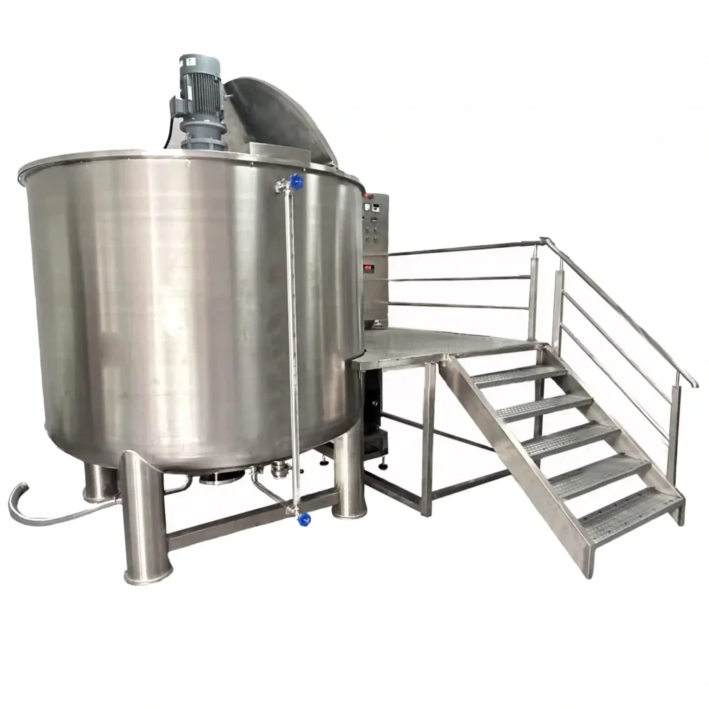
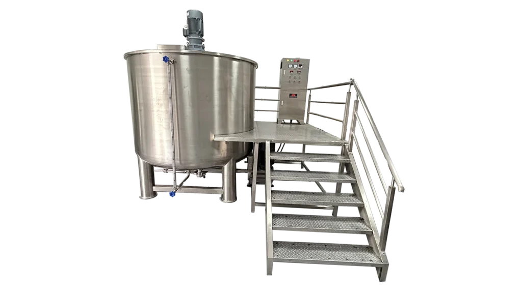
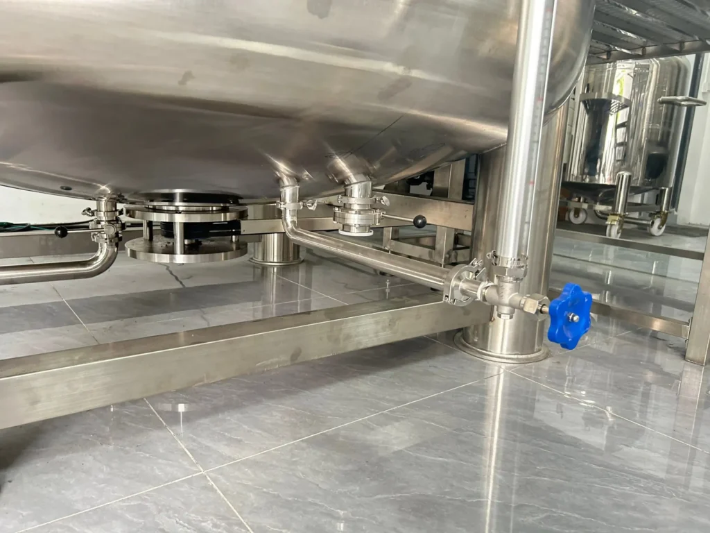
| Mixing tank | Outlet, bottom profile, agitator attachments, internal fittings, and lid interfaces | Inspect relevant contact areas and observe the specified drain-down |
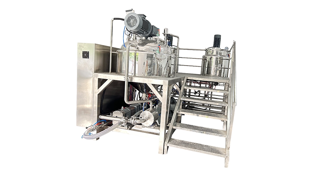
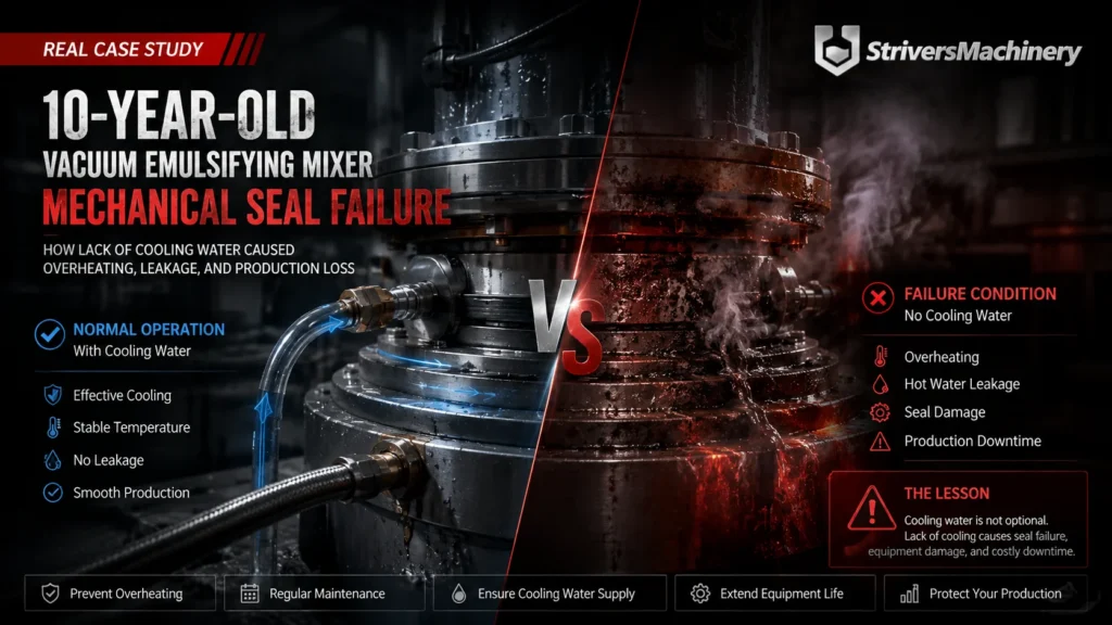
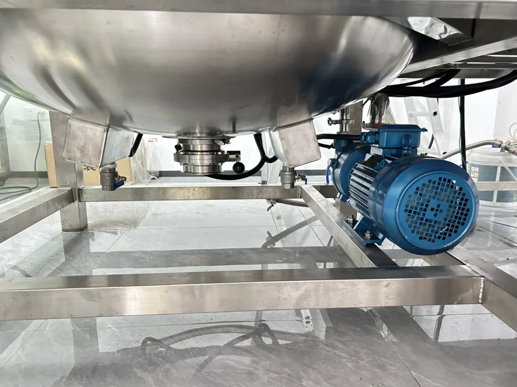
| Vacuum emulsifying mixer | Homogenizer path, seals, recirculation lines, lid grooves, and wetted vacuum connections | Trace each product and cleaning route, including normally closed sections |
| Valves and joints | Body cavities, seats, gaskets, alignment, and installation orientation | Review the actual design and inspect or disassemble under the approved procedure |
| Piping and instruments | Unused branches, sample points, reducers, supports, and sensor connections | Compare the installed route and geometry with the current drawing |
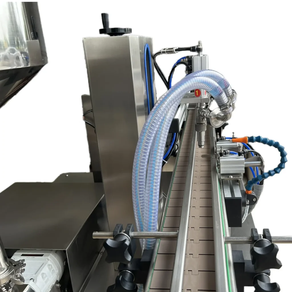
| Filling system | Hopper outlet, pumps, manifold branches, hoses, nozzles, and cutoff mechanisms | Compare cleaning conditions and findings across individual branches |
| CIP circuit | Spray obstruction, supply restrictions, return routing, trapped air, and drain points | Check the actual assembled configuration and recorded supply and return conditions |
Mixing Tanks: Check Drainage and Access
Observe what remains after the agreed draining procedure. Record the tank position, outlet condition, time, and liquid used for the check. A conical or sloped bottom may help, but the outlet and installed arrangement must support drainage.
A flat bottom is not automatically unacceptable, and a cone bottom is not an automatic pass. Review the actual retained locations and the cleaning access. An external jacket junction is relevant only if its construction affects the contact surface or another identified risk.
Our radius and transition guide explains local geometry. A 300L open-top tank provides direct access to some areas, while enclosed designs need other inspection arrangements.
Vacuum Mixers: Follow Every Wetted Route
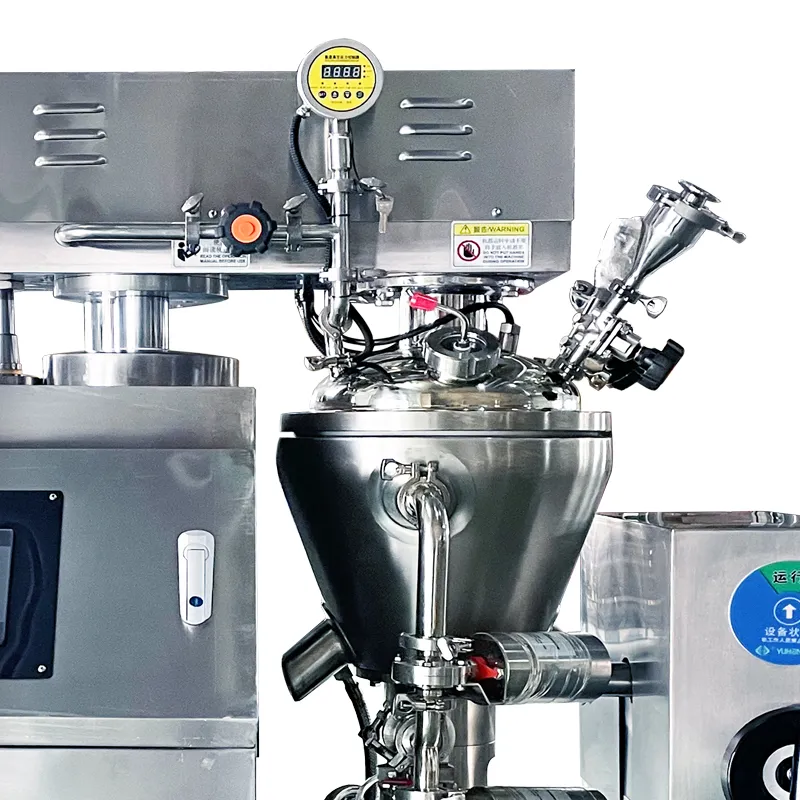
Review the homogenizer, seal region, outlet, lid connections, and any external circulation path. Identify which valves move during cleaning and which sections receive fluid. Components that are removable may need a separate cleaning and inspection step.
The vacuum mixer buying guide helps define these arrangements before purchase. A 20L laboratory mixer still needs a clear plan for attached tanks, piping, valves, and the main vessel.
Valves and Connections: Inspect the Inside
A standard ball valve can retain material in body cavities. Some designs provide specific cleaning features; others require removal and cleaning. Review the actual valve instructions, service conditions, and test results before deciding how it will be used.
Diaphragm and other hygienic valve designs also depend on orientation, installation, seals, and their intended cleaning method. The component name does not settle the complete assembly.
For clamp connections, check dimensions, alignment, gasket condition, and the assembled internal profile. Our clamp and flange guide explains why access and correct assembly matter alongside connection type.
Recommended Equipment

100 LITERS Hydraulic Lift Vacuum Emulsifying Machine for Cream, Lotion & Cosmetic Production
View Details
Instrument Branches and Piping
Check unused ports, bypasses, sampling connections, and instruments added after commissioning. Determine how each branch exchanges fluid, vents, drains, and gets cleaned. A flush-mounted design may reduce a branch, but the sensor face and seal still need review.
Our pH sensor installation guide explains the connection and service questions for one instrument type. Use the same discipline for temperature, pressure, conductivity, and level devices.
Changes to a water distribution system need the same attention. A passing sample at the treatment outlet does not establish the condition of every branch downstream.
Filling Systems: Compare the Branches
Trace the product-contact path from hopper to pump, manifold, hoses, and nozzles. Record valve positions and cleaning routes. One return-flow reading may not show the conditions in each manifold branch.
A rotary-lobe-pump filler illustrates a system with several product-contact sections. The pump selection guide helps identify the pump, connection, and cleaning requirements to review.
Separate Coverage from Cleaning Results
Coverage and Spray Shadows
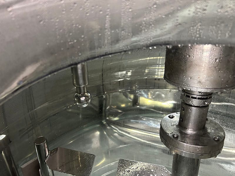
Check spray-device position, orientation, supply conditions, and obstructions. Shafts, baffles, lid fittings, and attachments can affect where liquid reaches. Use a suitable coverage protocol on the configuration actually supplied and installed.
A riboflavin coverage test uses a fluorescent marker and a defined rinse and inspection procedure. Remaining fluorescence helps identify locations needing investigation under that protocol. The test assesses coverage-related performance; actual soil removal needs its own suitable evidence.
Static spray balls, rotary heads, and jet devices have different operating characteristics. Select them for the vessel, soil, available supply, obstructions, and required cleaning action. Device type alone cannot rank the final coverage percentage.
Choose Tests for the Question
| Method | Useful For | Important Boundary |
|---|---|---|
| Visual inspection | Accessible gross residue, deposits, damage, and installation findings | Visibility and the inspection conditions limit what can be assessed |
| Fluorescent coverage test | Assessing spray coverage under a defined procedure | Does not establish removal of every product soil or microbial control |
| ATP monitoring | Rapid checks at defined locations using suitable site limits | Not a microbial count; residue, chemistry, and method suitability affect interpretation |
| Specific residue analysis or suitable TOC | Assessing relevant chemical or organic residues | Needs appropriate recovery, background, sensitivity, and acceptance criteria |
| Conductivity | Monitoring suitable ionic cleaning solutions or rinse endpoints | Cannot represent every nonionic residue or microorganism |
| Microbiological sampling | Investigating the specified microbial question at selected locations | Needs suitable collection, recovery, handling, and interpretation |
Swab and rinse describe sampling approaches, not a single test result. Swabbing can target an accessible location; rinsing can cover a wider path. Select the approach and analytical method together, with appropriate recovery and limits.
A defined ATP swab location can help localize a problem. Its reading still cannot identify a microorganism or substitute for a required microbiological test. Likewise, a normal conductivity reading cannot clear every organic residue.
Correct the Mechanism Behind the Finding
Improve Geometry, Exchange, or Access
Possible changes include removing an unused branch, changing a connection, relocating an instrument, correcting a gasket, improving drainage, or adding planned disassembly. Confirm how the change addresses the observed problem and how the result will be checked.
For surface defects or corrosion, review the material, fabrication, operating chemistry, and repair method. Our 304 versus 316L guide provides the material context; polishing a part alone may leave the underlying cause unresolved.
A mobile homogenizing tank needs its valves, outlets, and transfer connections included in that review, not just the vessel wall.
Improve the Cleaning Route
Confirm flow reaches the required sections at the specified valve positions. Check restrictions, trapped air, return behavior, and the operating condition of cleaning devices. Pipe flow, vessel spray, and valve-cavity cleaning need different assessments.
Time, action, chemistry, and temperature interact, but they are not freely interchangeable. Adjust them within the method’s supported range and material limits. A higher temperature or concentration can introduce other problems.
Cleaning out of place may involve manual work or a dedicated washer for removed parts. Decide which parts come out, how they are cleaned, how they are inspected, and how reassembly is checked.
Keep Sanitization and Sterilization Distinct
Related Solutions


Cleaning removes the relevant soil. Sanitization and sterilization have different microbial-control objectives and need their own defined conditions. A steam or chemical treatment cannot be assumed to compensate for inaccessible residue.
Where ozone or another chemical treatment is selected, define material compatibility, residual control, safety, and readiness for the next use. Keep these choices within the complete process and quality plan.
A Practical Investigation Sequence
- Define the finding. Record its location, product, history, method, and acceptance criterion.
- Map the current equipment. Include valves, branches, instruments, return paths, and modifications.
- Review operating conditions. Compare the intended cleaning program with actual readings and sequence.
- Inspect safely. Use approved shutdown, isolation, depressurization, and access arrangements.
- Select the checks. Match coverage, residue, drainage, or microbial methods to the question.
- Assess the evidence. Identify the supported cause and unresolved possibilities.
- Approve and make the correction. Update the relevant drawing, procedure, and responsibilities.
- Retest the affected requirements. Check the correction under the agreed conditions.
- Record release and follow-up. Keep results and define what triggers another review.
For new equipment, agree these checks before purchase. Our factory acceptance testing guide explains how to record conditions, criteria, findings, and open items. Site testing should cover the installed conditions that factory tests cannot reproduce.
Four Project Lessons
Vacuum-Port Geometry and Corrosion
A cosmetic manufacturer had an intermittent vacuum leak in an emulsifying mixer. The investigation traced the fault to retained condensation and corrosion around a poorly arranged vacuum-port connection, affecting the connection’s sealing condition.
The affected section was replaced and the connection geometry corrected. This resolved the reported leak. The lesson is to investigate the connection and leakage path alongside the gasket, rather than treating every vacuum problem as a consumable-seal fault.
Uneven Cleaning Across a Filling Manifold
A food manufacturer found residue at certain heads on a multi-nozzle filler while others cleaned adequately. The investigation identified uneven cleaning-flow distribution across the manifold branches.
Revising the distribution geometry corrected the residue pattern. Comparing individual branches revealed a problem that a single overall flow reading had missed.
A Spray Shadow Around an Agitator Mount
A pharmaceutical storage-tank project repeatedly showed fluorescent marker remaining near the agitator-shaft penetration during coverage testing. The shaft and mounting arrangement obstructed the existing spray pattern.
Repositioning the spray device and adding a directed secondary nozzle resolved the observed coverage failure on retest. That result confirmed the coverage correction; the wider cleaning assessment still followed the project’s defined requirements.
A CIP Upgrade Shortened Cleaning by About 35%
A chemical manufacturer reviewed several tanks after long cleaning cycles and inconsistent cleaning results. The review identified problematic instrument branches and spray coverage that had not been reassessed after equipment changes.
Correcting the branches and improving the spray arrangement allowed the cleaning cycle to be shortened by roughly 35%, with more consistent cleaning results. The facility also reported lower water and cleaning-chemical use.
These are project outcomes, not a saving promised for every installation. The useful principle is to correct the demonstrated flow and coverage problems, then establish an effective cycle for the revised arrangement.
Decision Guide
Keep the Inspection Plan Current
Review cleaning-critical changes: a new instrument, different valve, altered pipe route, replaced gasket, new product, changed chemical, or revised cycle. Decide which checks need repeating and retain the evidence for the current configuration.
Our retrofit guide helps organize modifications. The mixer maintenance guide covers routine equipment information useful during an investigation.
Include access, drains, and cleaning services in the site layout. Our installation guide and utilities checklist explain the preparation to settle before commissioning.
Use Standards and Monitoring for Their Actual Purpose
Identify applicable requirements by product, equipment, market, and project scope. ASME BPE, EHEDG guidance, and other documents can support engineering decisions where relevant. Compliance with a selected dimension or a component certificate does not establish the cleanability of the complete installation.
Flow, temperature, pressure, and conductivity records help show whether a defined cycle ran within its limits. They do not directly show every surface or residue. Models and simulations can guide a review when their assumptions are appropriate; physical inspection and suitable tests remain part of confirming the result.
How StriversMachinery Can Help
StriversMachinery manufactures core mixing equipment in-house and coordinates complementary equipment from long-term partner factories. For our vacuum emulsifying mixers and associated systems, we discuss the product path, access, cleaning arrangement, connections, and agreed inspection scope.
Send the current drawing, photos of the suspected location, product details, cleaning sequence, operating records, and test findings to [email protected]. A useful proposal identifies the correction, included work, checks, and remaining site responsibilities.
Our supplier responsibility guide helps define those roles. The quotation scope checklist helps clarify whether inspection, trial materials, installation, and retesting are included.
For a new purchase, use the equipment buying guide to describe the product and cleaning requirements before comparing machines. Clear inputs make it easier to design for cleanability and verify the result.
Technical References
- ASME: Branch Leg Study for Bioprocessing Equipment
- STERIS: Riboflavin Coverage Test
- Hygiena: HACCP Cleaning and Sanitation Verification White Paper
- FDA: Questions and Answers on CGMP Requirements — Equipment
- FDA: Questions and Answers on CGMP Requirements — Laboratory Controls
- Sani-Matic: Spray Ball and Supply Tube Instructions — Verifying Spray Effectiveness
These sources support branch-flow, coverage, monitoring, and sampling principles. FDA drug-manufacturing guidance is used for its methodological context, not as a universal cosmetic requirement. The references do not certify the illustrated equipment or independently verify the project cases.