

100 LITERS Hydraulic Lift Vacuum Emulsifying Machine for Cream, Lotion & Cosmetic Production

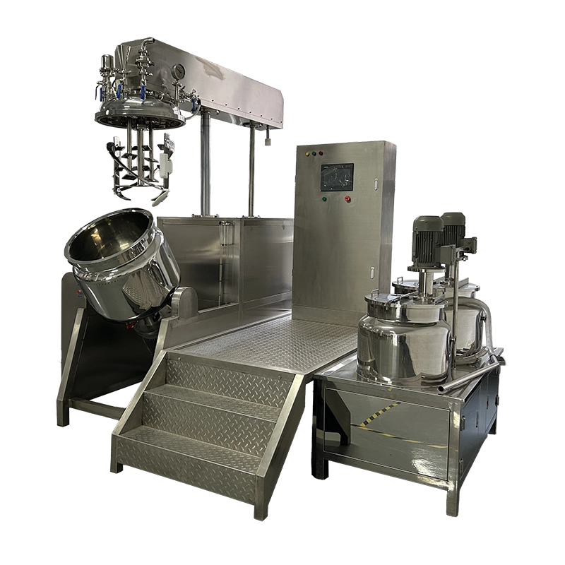
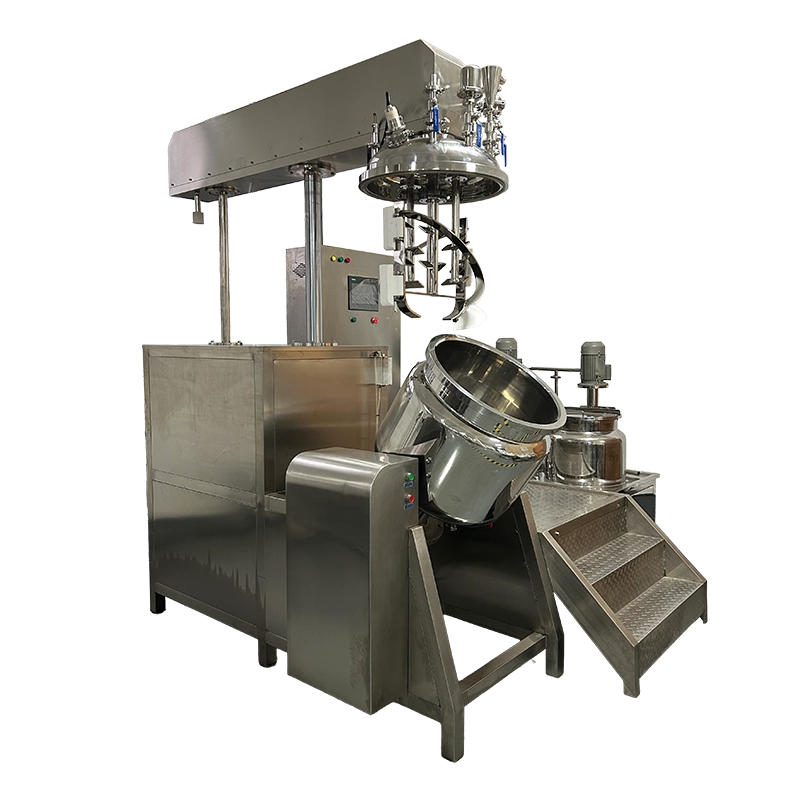
The 100L hydraulic lift vacuum emulsifying machine is a batch-processing system for creams, lotions, and cosmetic formulations. A 100L working vessel combines helical ribbon agitation, PTFE wall scraping, bottom-entry high-shear homogenization, and vacuum processing. Integrated oil and water preparation pots support separate phase preparation, while the hydraulically lifted head and electric tilting system provide access and discharge flexibility for cosmetic production.
| Total Capacity (L) | 120 | Discharge Valves | Flush Bottom Valve |
| Working Capacity (L) | 100 | Lid Lifting System | Hydraulic Lifting System (Automatic) |
| Min Batch Size (L) | 20 | Mechanical Seal Brand | Single Mechanical Seal (John Crane/EagleBurgmann Optional) / Double Mechanical Seal (EagleBurgmann) |
| Structure Type | Triple Layer (with Jacket & Insulation) | Tilting System | Electric Tilting |
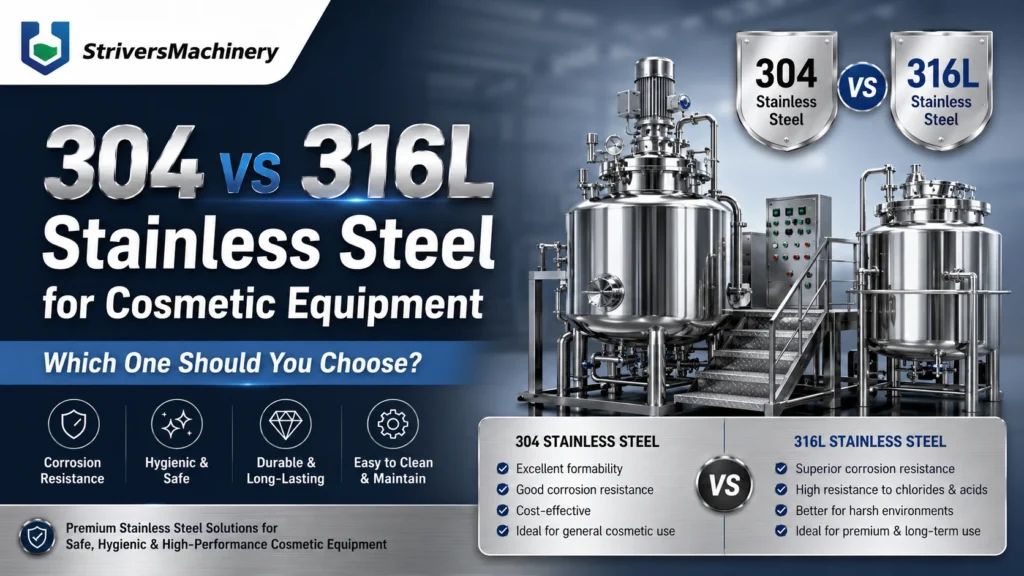
| Contact Material | SUS316L Stainless Steel | Types of Upper Heads | Hydraulic Lifting Head / Fully Sealed Vacuum Head |
| Non-contact Material | SUS304 Stainless Steel | Top Openings & Accessories | Vacuum Port / Vacuum Feeding Port / Powder Feeding Port / Liquid Inlet / Fragrance Addition Port / Manway / Sight Glass with Wiper / LED Inspection Light / CIP Spray Ball / Vent Filter / Vacuum Gauge / Pressure Sensor / Compressed Air Inlet |
| Surface Finish | Interior Mirror Polish (Ra ≤ 0.4 μm) & Exterior Satin/Matte Finish | Motor Brand | SEW / ABB / Siemens / Top-Tier Chinese Brands (Optional) |
| Jacket Design Pressure (MPa) | 0.3 | vem_electrical_components | Schneider / Siemens / Omron (Optional/Customizable) |
| Main Tank Mixer Type | Helical Ribbon Agitator | Oil & Water Pot | Equipped with Integrated Oil & Water Pre-treatment Pots |
| Mixing Speed (rpm) | 0–63 rpm | Oil & Water Pot Capacity (L) | Oil: 50L / Water: 80L |
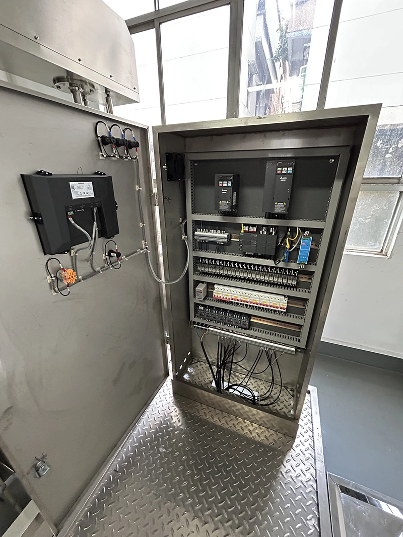
| Mixing Motor Power (kW) | 1.5 | vem_control_system | PLC Control System with Weinview / EasyView HMI Touch Screen |
| Frequency Control | Variable Speed with VFD (Delta, Siemens, ABB, Schneider, Optional) | Fully Raised Height (mm) | 2800 |
| Scraper System | Wall-Scraping PTFE Scrapers | Platform & Ladder | SUS Anti-slip Platform with Guardrails & Ladder |
| Homogenizer Position | Bottom-entry Homogenizer | Voltage | Configurable to local grid (110V–480V, 50/60Hz, Single or 3-Phase) |
| Homogenizer Type | High Shear Stator-Rotor Homogenizer | Total Power (kW) | 30.5 |
| Homogenizer Power (kW) | 4 | Air Pressure | No Compressed Air Required |
| Homogenizer Speed (rpm) | 0–3000 rpm (Variable Speed) | Drive Type | Electric |
| Max Processing Viscosity (mPa·s / cP) | 50,000 | Installation Type | Platform-mounted |
| Heating Method | Electric Heating via Jacket / External Steam Heating (Optional) | Automation Level | Fully Automatic |
| Cooling System | Tap Water / Cooling Tower Circulation (Chilled Water / Glycol Circulation Optional) | Control System | PLC + HMI Touch Screen Control |
| Water Chiller | External Water Chiller Unit (Optional) | PLC System | Siemens |
| Temperature Control Accuracy | ±1°C | HMI / Touch Screen | Siemens |
| Vacuum Degree (MPa) | -0.09 | Control & Interaction Systems | Fully Automated (High-Tech / Industry 4.0) |
| Vacuum Pump Brand | High-quality domestic/joint venture brands | Machine Dimensions(L*W*H)mm | 2120*800*2240MM |
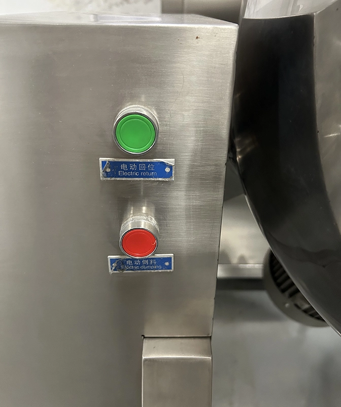
| Discharge Method | Electric/Manual Tilting Discharge / Bottom Valve Discharge (Optional Air Pressure Assist) / External Pump Transfer System | Machine Weight (kg) | 1200 |
Product Gallery
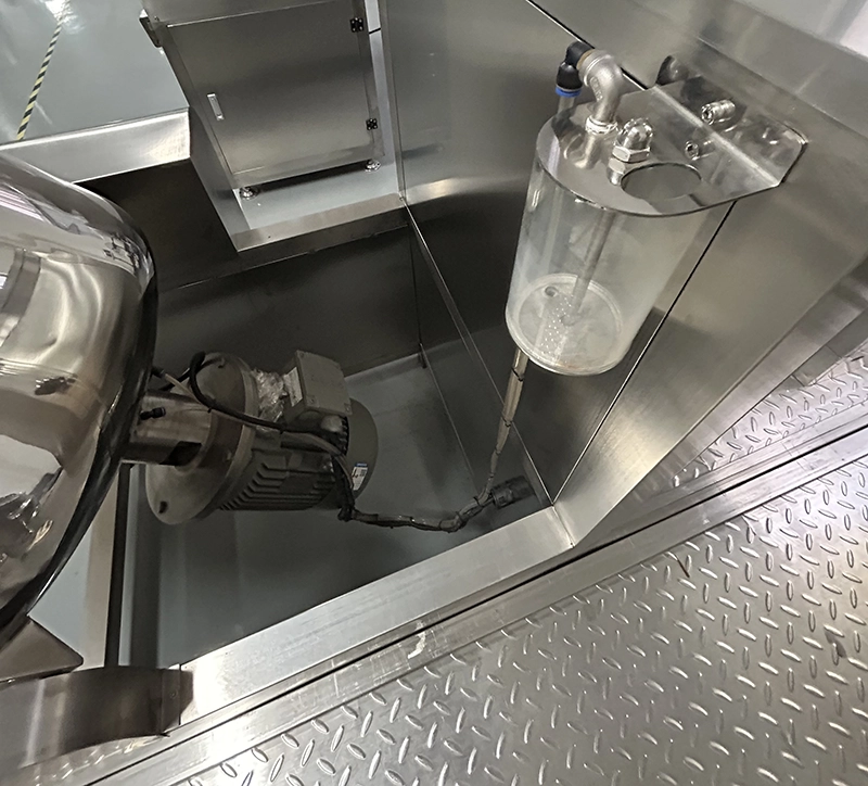
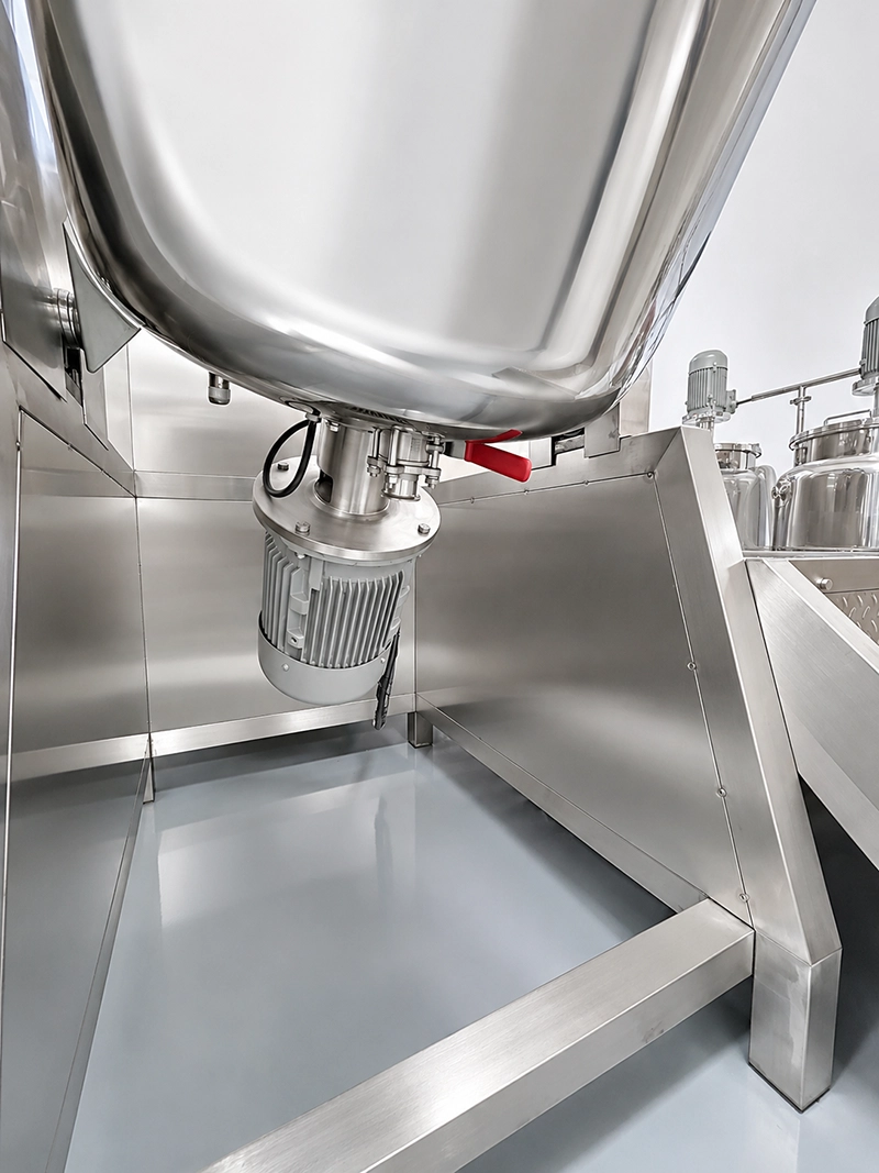
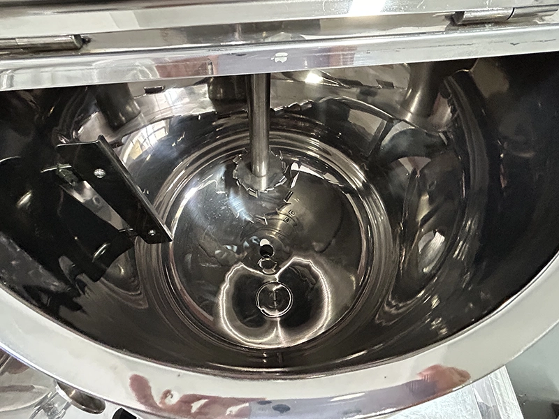
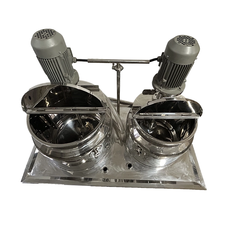
Product Video
Product Overview
This 100L system brings phase preparation, bulk mixing, high-shear emulsification, thermal processing, and vacuum deaeration into one coordinated equipment arrangement. It is intended for manufacturers evaluating a dedicated batch platform for creams, lotions, and related cosmetic products.
The main vessel has a 120L total capacity and a specified 100L working capacity. Its listed minimum batch size is 20L, although suitability at the lower end depends on the formulation and whether the mixing and homogenizing elements engage the product effectively. These figures describe vessel operating limits, rather than a guaranteed finished-product yield.
An integrated 50L oil pot and 80L water pot support separate preparation of formulation phases. The main tank uses a helical ribbon agitator with PTFE wall scrapers, together with a bottom-entry rotor-stator homogenizer. Jacket heating and circulation cooling allow thermal processing to be incorporated into the batch sequence.
The hydraulic lifting head opens the vessel for access, while electric tilting and a flush bottom valve provide different discharge arrangements. SUS316L product-contact construction and the specified polished interior support cleanability.
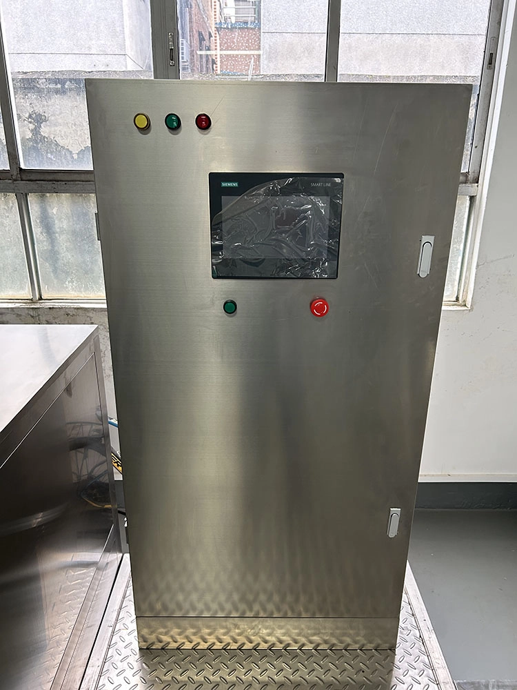
PLC and HMI controls provide the operating interface. Final component brands, process functions, and optional equipment should be defined in the agreed technical configuration.
Machine Configuration
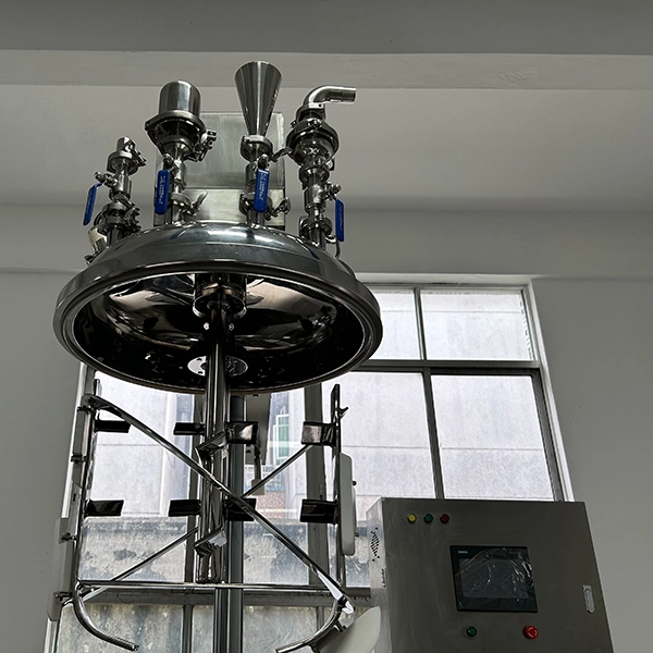
The system consists of a main emulsifying vessel, integrated oil and water preparation pots, a hydraulic head-lifting assembly, an electric tilting mechanism, and a platform with guardrails and a ladder.
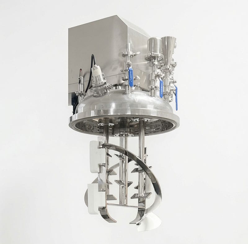
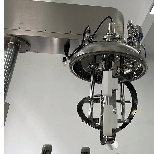
Inside the main vessel, the helical ribbon agitator provides bulk movement, while PTFE scrapers act along the vessel wall. A separate bottom-entry rotor-stator homogenizer supplies localized high-shear processing. Independent variable-speed drives allow these mixing functions to be adjusted for the process.
The triple-layer vessel incorporates a thermal jacket and insulation. Electric jacket heating is specified, with external steam heating available as an option. Cooling uses an external circulation supply selected for the required duty.
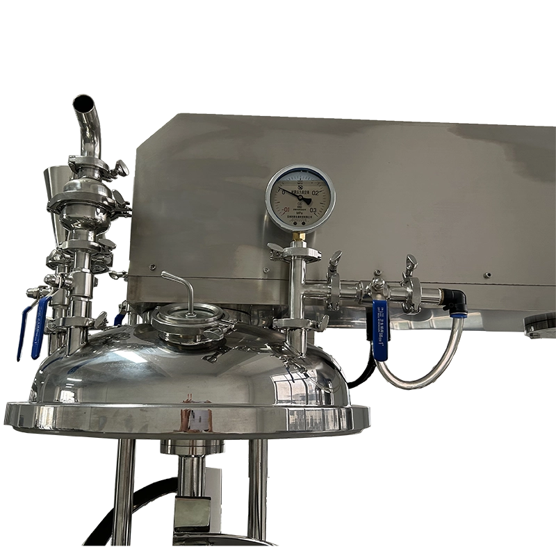
The vacuum system connects to the sealed processing vessel. Top-mounted accessories include feeding ports, observation provisions, instrumentation, and a CIP spray ball.
PLC and HMI controls coordinate the supplied functions. Motor, drive, electrical, mechanical-seal, and HMI selections must match the final order.
Key Features
Hydraulic head lifting opens the vessel for cleaning, inspection, and access
Helical ribbon agitation provides bulk movement during batch preparation and processing
PTFE wall scrapers sweep product along the vessel’s internal wall
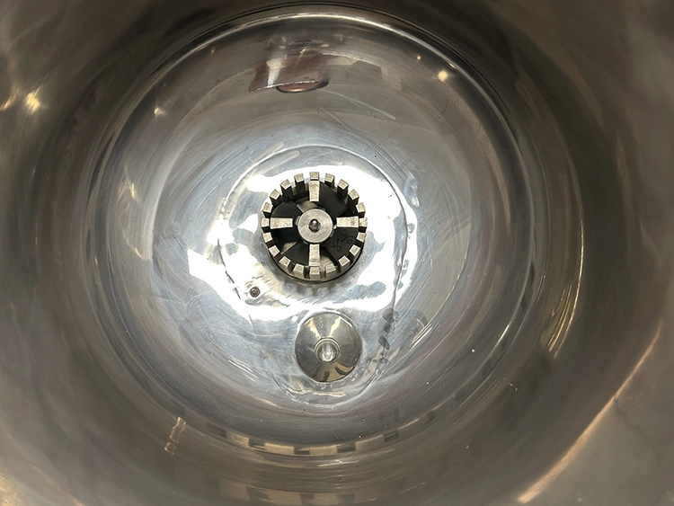
Bottom-entry rotor-stator homogenizer provides a separate high-shear processing stage
Independent variable-speed mixing and homogenization support formulation-specific operating settings
Integrated oil and water pots allow separate formulation phase preparation
Jacket heating and circulation cooling support controlled thermal processing
Vacuum processing supports air removal when appropriate for the formulation
Electric tilting and bottom discharge provide alternative product-removal arrangements
PLC and HMI controls provide a central interface for supplied functions
Applications
- Cosmetic Cream & Lotion, and Skin Care
- Hair Care, Personal Care & Body Wash
- Pharmaceutical & Ointment Products
Recommended Machines


Working Principle
Production begins with preparation of the ingredients and formulation phases. Where the recipe requires separate oil and water preparation, the integrated auxiliary pots are used before the phases enter the main vessel. The actual charging order, preparation temperatures, and transfer sequence must follow the approved formulation.
In the main tank, the helical ribbon agitator moves the bulk product through the vessel. PTFE scrapers sweep the internal wall, helping return wall-adjacent material to the moving batch. Jacket heating or cooling is applied according to the product’s thermal requirements.
The bottom-entry rotor-stator homogenizer subjects material passing through its working zone to high shear. This stage supports emulsification and dispersion where the formulation requires it. Homogenizer speed and operating duration must be selected for the product; maximum speed is not automatically the correct setting.
Vacuum can be applied during an appropriate stage to support air removal. Vacuum use must account for foaming, volatile ingredients, temperature, and the formulation’s behavior under reduced pressure.
After the required processing and cooling stages, product is discharged using the agreed arrangement. Electric tilting, bottom-valve discharge, and external pump transfer should be selected according to product flow and downstream handling.
The hydraulic head is raised only after the vessel has been safely brought to the condition required by the operating instructions. It provides access between processing operations rather than replacing the specified cleaning or maintenance procedure.
Optional Upgrades & Configurations
| Warranty | 24 Months | Payment Terms | 40% T/T Deposit, 60% Balance Before Shipment (Alibaba Trade Assurance Available) |
| Lead Time | 20–30 Working Days | Packaging | Standard Export Fumigation-Free Wooden Case |
Recommended Accessories


After-Sales & Technical Support
🔧 Common Problems
Potential symptoms to monitor include uneven product appearance, visible unincorporated ingredients, persistent air bubbles, product collecting along the vessel wall, unstable vacuum indication, and temperature readings that do not follow the intended process. Operators may also observe unusual noise, vibration, leakage around a seal or connection, reduced discharge flow, or inconsistent movement during head lifting or vessel tilting. These are inspection topics for the installed system rather than documented faults of this particular machine. Their significance depends on the formulation, batch volume, operating settings, and selected configuration. Record the affected process stage and observed condition before making adjustments. An acceptable-looking surface alone should not be used to confirm that the complete batch meets its processing requirements.
🛠 Troubleshooting
Problem: Ingredients remain visibly unincorporated Possible Cause: Charging sequence, batch volume, or mixing settings differ from the approved process Recommended Solution: Compare the batch record with the validated method and confirm that the processing elements engage the product effectively before changing settingsProblem: Air bubbles remain after vacuum processing Possible Cause: Air is being introduced during charging or mixing, the vacuum stage is unsuitable, or the vacuum system needs inspection Recommended Solution: Review the process sequence and vacuum indication. Isolate the equipment before inspecting seals, connections, or vacuum componentsProblem: Product temperature does not follow the intended profile Possible Cause: Utility conditions, thermal settings, sensor performance, or product circulation differ from the approved conditions Recommended Solution: Check displayed values and utility availability, then arrange qualified inspection according to the supplied documentationProblem: Unusual noise, vibration, or seal leakage occurs Possible Cause: An abnormal operating condition or a component requiring inspection Recommended Solution: Stop the affected equipment and follow the supplier’s isolation and inspection procedure before restartingProblem: Product discharges slowly Possible Cause: Product flow behavior, discharge temperature, outlet condition, or transfer arrangement is unsuitable Recommended Solution: Review the approved discharge method. Do not apply air pressure or increase vessel pressure without explicit authorization in the equipment documentation
🧼 Cleaning Method
Confirm the cleaning procedure|Use a procedure approved for the formulation residue, product-contact materials, seals, and installed equipmentDischarge the remaining product|Remove bulk product through the agreed discharge arrangement before beginning cleaningMake the system safe|Bring the vessel to the required temperature and pressure condition and isolate equipment as instructedRemove accessible residue|Use approved tools and methods without damaging the polished interior or PTFE scrapersPerform the approved preliminary rinse|Use the specified medium and collection arrangement for the product and installationApply the cleaning stage|Use the approved chemistry, concentration, temperature, and contact conditions without substituting assumed valuesClean the spray-ball circuit|Operate it only through the supplied or separately approved cleaning arrangementClean components requiring separate attention|Follow instructions for valves, ports, seals, and any removable product-contact partsComplete rinsing and any required sanitization|Follow the approved procedure and its acceptance criteriaInspect and release the equipment|Check cleanliness, drainage, component reassembly, and readiness before the next batch
📋 Maintenance
Isolate all relevant energy|Secure electrical, hydraulic, thermal, vacuum, and any optional pressure sources according to the supplied instructionsConfirm a safe vessel condition|Verify the required temperature and pressure condition before opening or servicing the equipmentInspect the agitator and scrapers|Check accessible components for wear, damage, attachment condition, and product buildupInspect the homogenizer|Follow the supplier’s procedure for checking the rotor-stator assembly without making unsupported clearance adjustmentsInspect the mechanical seal|Check for leakage and verify the condition of any specified cooling or support arrangementInspect the lifting and tilting systems|Have qualified personnel examine hydraulic connections and moving assemblies according to the maintenance documentationInspect valves and gaskets|Check product-contact closures and connections for deterioration, leakage, or residueInspect vacuum and thermal systems|Check accessible connections, indicators, and utility arrangements using the approved methodsService specified components|Use the approved parts, lubricants, methods, and maintenance intervals for the delivered configurationVerify operation after maintenance|Complete the required functional checks and record service findings before returning the machine to production
⚙️ Installation
Verify the delivered system|Check vessel capacities, selected components, accessories, and utility requirements against the agreed technical specificationPosition the equipment|Place the platform-mounted system according to the approved factory layout and support requirementsConfirm the lifting envelope|Check the full head travel and required overhead clearance against the installation drawingInspect the supplied assemblies|Have qualified personnel check the condition and installation of the platform, lifting system, vessel, and auxiliary potsConnect the electrical supply|Use qualified personnel and follow the delivered electrical rating, wiring documentation, and protective requirementsConnect thermal utilities|Install the selected heating and cooling connections according to the approved configurationConnect seal-support utilities|Provide any cooling or support connections required by the selected mechanical sealArrange discharge connections|Install the agreed receiving or transfer arrangement without imposing unsupported loads on the vessel connectionsComplete commissioning checks|Follow the supplier’s procedure for controls, protective functions, lifting, tilting, agitation, vacuum, and thermal systemsTrial the agreed process|Use representative material and documented acceptance criteria under the approved commissioning plan
🔩 Spare Parts
Why Choose This Machine
– Combines complementary mixing actions. Bulk agitation, wall scraping, and localized high shear address different processing needs within the same vessel.
– Supports separate phase preparation. The integrated oil and water pots allow preparation tasks to be organized around formulations requiring distinct phases.
– Provides a defined production scale. The 100L working capacity offers a clear basis for batch planning, while remaining distinct from the 120L total vessel volume.
– Improves access planning. Hydraulic head lifting opens the vessel for inspection and cleaning access, subject to the required overhead clearance.
– Offers discharge flexibility. Tilting, bottom discharge, and separately specified pump transfer can be evaluated against product behavior and the receiving equipment.
– Supports thermal process control. The jacket allows heating and cooling duties to be incorporated into the formulation sequence.
– Makes configuration choices explicit. Heating source, cooling supply, mechanical seal, and controls can be agreed around the actual production requirement.
– Supports production-line integration. The system can be assessed alongside water treatment, bulk storage, transfer, and filling equipment.
These advantages describe the engineering arrangement. Finished-product stability, droplet size, batch time, and labor savings require formulation-specific evidence before being presented as measured results.
Frequently Asked Questions
Installation Requirements
The platform-mounted system weighs approximately 1200 kg as supplied. Floor and support suitability must be assessed for the complete installed condition, including product, auxiliary equipment, and applicable loads.
Confirm the electrical rating of the delivered unit against the site supply. The listed total power is 30.5 kW, but connection sizing and protective arrangements must follow the final electrical documentation.
Provide the selected cooling supply, return or drainage arrangement, and any required mechanical-seal cooling connections. External steam heating requires separately confirmed utility and protection provisions.
The standard configuration is listed as requiring no compressed air. Any optional pneumatic or pressure-assisted function changes the utility scope and must be assessed separately.
Related Articles


Technical Buyer's Handbook & Deep Insight
Ready to Get a Quote?
Contact our team directly for pricing, customization options, and delivery timelines.
💬 WhatsApp Us NowGet Your Download Link
Please fill in your details and we'll send the download link to your email.