

5000L Single Layer Homogenizer Mixing Tank for Liquid Soap, Detergent, Shampoo & Cosmetic Batch Production
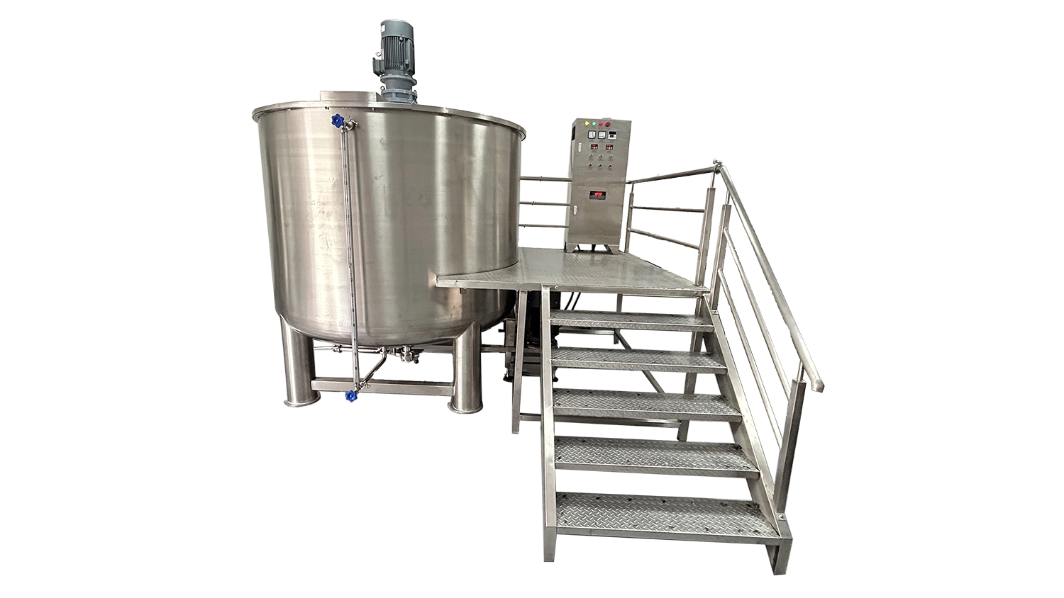
The 5000L Single Layer Homogenizer Mixing Tank is an atmospheric batch-processing vessel for liquid soap, detergent, shampoo and related flowable formulations. It combines bulk agitation with bottom-entry high-shear mixing for manufacturers handling larger production batches. Within the homogenizing mixing tanks range, this model suits processes that need ingredient incorporation and product uniformity without an integrated heating jacket or vacuum-processing system.
| Tank Structure | Single Layer (Storage / Mixing) | Rotor Stator Type | Single-Stage Rotor Stator |
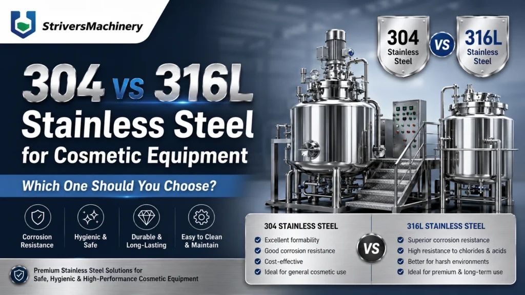
| Contact Material | SUS316L Stainless Steel | Types of Upper Heads | Flat Head / Open Top Design |
| Outer Material | SUS304 Stainless Steel | Discharge Type | Bottom Valve Discharge (Optional External rotor pump/diaphragm pump/screw pump) |
| Surface Finish | Inside Mirror Polished & Outside Brushed Finish | Discharge Valves | Butterfly Valve |
| Surface Roughness | Ra ≤ 0.4 μm (Sanitary Grade) | Connection Type | Tri-Clamp |
| Full Capacity (L) | 6000 | Motor Brand | SEW / ABB / Siemens |
| Working Capacity (L) | 5000 | Voltage | Configurable to local grid (110V–480V, 50/60Hz, Single or 3-Phase) |
| Main Mixing Type | Propeller | Total Power (kW) | 28 |
| Agitation Direction | Single Direction | Drive Type | Electric |
| Mixing Speed (rpm) | 1-63 | Installation Type | Floor-Standing |
| Mixing Power (kW) | 5.5 | Automation Level | Semi-Automatic |
| Frequency Converter | Variable Speed with VFD (Delta, Siemens, ABB, Schneider, Optional) | Electrical Components | Schneider / ABB / Siemens / Omron / Fuji /Mitsubishi (Optional) / Top-tier Chinese Brand: DELIXI / CHINT / People Electric / TENGEN |
| Homogenizer Position | Bottom-Entry Homogenizer | Control System | Push Button Control |
| Homogenizer Speed (rpm) | 0–3000 rpm (Variable Frequency Control) | Machine Dimensions(L*W*H)mm | 3350*3150*2768 |
| Homogenizer Power (kW) | 22 | Machine Weight (kg) | 1600 |
Product Gallery



Product Video
Product Overview
This floor-standing tank provides a large-batch preparation stage between ingredient charging and downstream storage or filling. Its propeller agitator moves the bulk product, while the bottom-entry rotor-stator homogenizer applies localized high shear. The two mixing functions allow operators to adjust the processing sequence around ingredient incorporation, dispersion and final blending.
For manufacturers of liquid detergents and household cleaning products, the machine is a candidate for formulations that can be processed without controlled jacket heating or cooling. Shampoo, body wash, liquid hand soap and compatible cosmetic liquids may also be evaluated through the hair care and body wash production application range.
Lotion, sanitizer and disinfectant applications require a separate formulation review. Products needing heated phase preparation, vacuum deaeration, hazardous-area equipment or materials beyond the confirmed compatibility range should not be selected from the product name alone.
The single-layer construction keeps the vessel focused on mixing duty. Product-contact surfaces are specified as SUS316L stainless steel with a mirror-polished interior. A bottom butterfly valve provides discharge, with external pump transfer available as an optional arrangement. The machine operates through push-button controls with variable-speed adjustment rather than an assumed automatic recipe sequence.
Machine Configuration
The assembly combines an atmospheric single-layer vessel, a top-mounted propeller mixing system and a bottom-entry single-stage rotor-stator homogenizer. Bulk agitation carries material through the vessel, while the homogenizer processes material entering its working zone.
Variable-frequency control provides speed adjustment for the mixing duties. The push-button control arrangement supports operator-led charging, processing and discharge. The final electrical schedule should identify the selected motors, drives and switching components from the supplied brand alternatives.
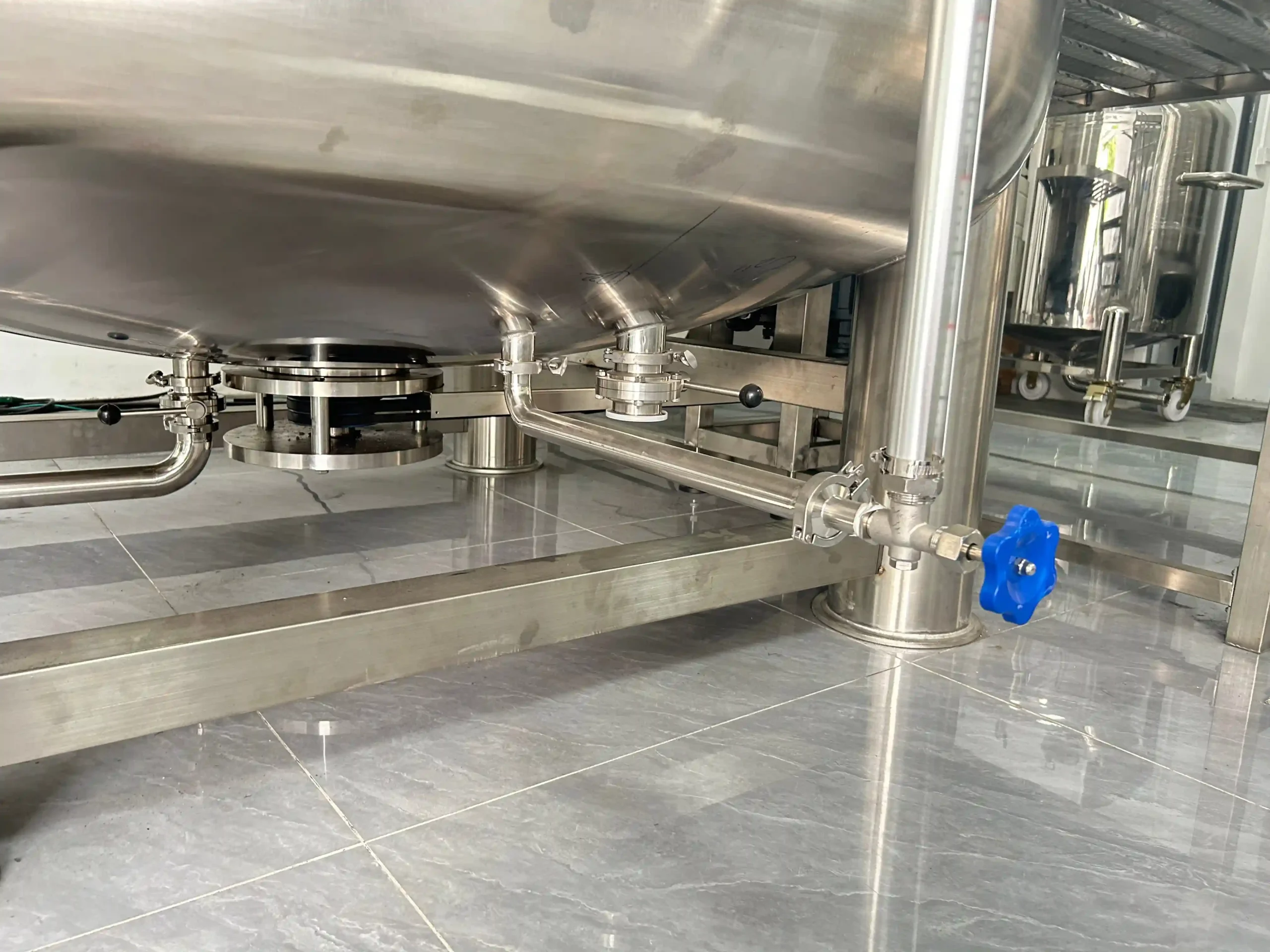
The flat-head/open-top arrangement provides the specified charging and access format; the final drawing should define the cover layout and operating protection. Tri-clamp connections support removable process connections, and the bottom butterfly valve connects the batch vessel to the receiving process.
Optional external rotor, diaphragm or screw pump transfer should be selected against the product and pipework. Integrated jacket heating, active jacket cooling, vacuum processing, wall scraping and automatic CIP are not included in the supplied configuration.
Key Features
- Bulk agitation and localized high shear serve different stages of ingredient incorporation.
- Adjustable processing speeds accommodate changes in formulation sequence and product behavior.
- Single-layer construction suits mixing duties without integrated thermal-processing requirements.
- Polished product-contact surfaces support residue inspection during product changeovers.
- Removable tri-clamp connections facilitate access to connected product pathways.
- Bottom discharge provides a direct connection to receiving or transfer equipment.
- Optional pump transfer accommodates downstream layouts beyond gravity discharge.
- Push-button operation keeps routine process decisions under direct operator control.
Applications
- Detergents, Liquid Washing & Household Cleaning
Recommended Machines
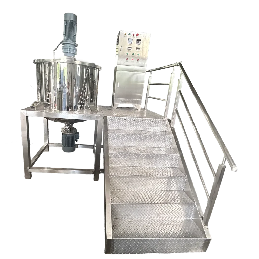
500L Semi-Open Liquid Soap & Shampoo Making Machine with Bottom Water-Cooled Homogenizer & Operation Platform
View Details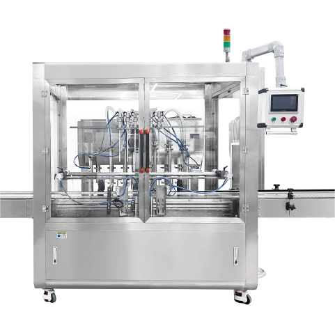
6-Head Automatic Gear Pump Filler for Cosmetic CREAM&Liquids | High-Viscosity Lotion & Shampoo Filling Machine
View Details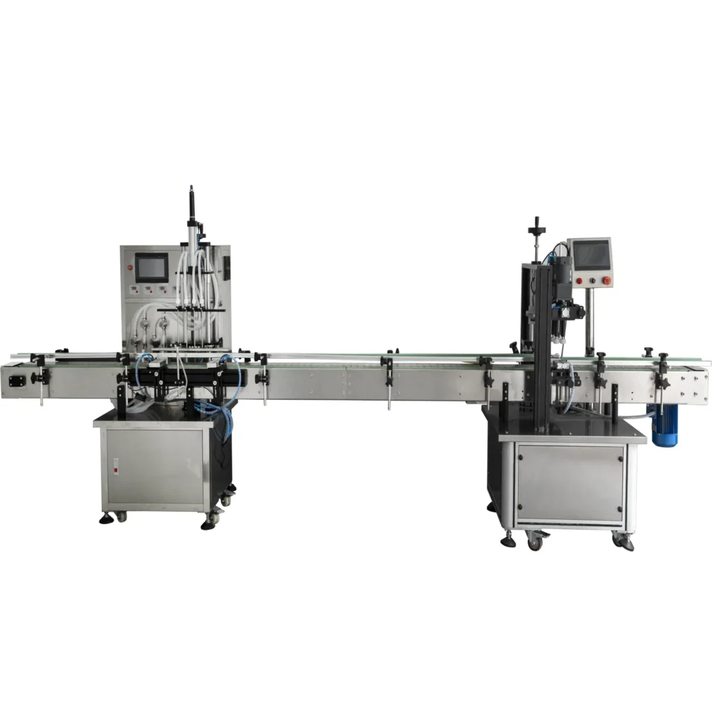
Working Principle
Production starts with charging the vessel according to the approved formulation sequence. The initial liquid level must satisfy the manufacturer’s operating requirements before either mixing system starts. Ingredient order depends on the product: a detergent blend, a polymer-thickened shampoo and a flowable lotion may require different preparation methods.
The propeller agitator establishes bulk movement through the batch. As ingredients enter, this circulation distributes them away from the charging area and brings material toward the bottom homogenizer. The effectiveness of that movement depends on the actual impeller geometry, liquid level and product viscosity.
When high shear is required, the bottom rotor turns within its stator. Material passing through the working zone experiences shear that supports dispersion and the breakdown of compatible agglomerates. This action does not establish a guaranteed particle size, emulsion stability or processing time for every formulation.
The operator adjusts the processing sequence and speeds to the product response. Some ingredients may need a high-shear incorporation stage followed by gentler blending; shear-sensitive ingredients may require a different sequence. Foaming, product temperature and batch appearance should be monitored throughout processing.
After the batch meets its agreed quality checks, product leaves through the bottom valve. Where gravity flow is insufficient or the receiving equipment is remote, a separately selected external pump can transfer the batch. The process ends with controlled product removal and the approved cleaning procedure. No heating, cooling or vacuum stage should be inferred from the homogenizing function.
Optional Upgrades & Configurations
| Warranty | 24 Months | Payment Terms | 40% T/T Deposit, 60% Balance Before Shipment (Alibaba Trade Assurance Available) |
| Lead Time | 15–20 Working Days | Packaging | Standard Export Fumigation-Free Wooden Case |
After-Sales & Technical Support
🔧 Common Problems
During operation, possible observable symptoms include differences in product appearance between samples, visible streaks after ingredient addition, persistent agglomerates, uneven surface movement, localized ingredient accumulation, excessive foam, retained air, unexpected viscosity differences, abnormal vibration, unusual drive noise, motor or VFD trips, unstable speed response, leakage around a product seal or connection, and reduced discharge flow. Operators may also observe product remaining around the bottom assembly after emptying, visible residue following cleaning, or different results between successive batches made to the same nominal recipe. These symptoms should be recorded with the batch volume, ingredient stage, mixing settings and operating conditions. They are potential observations rather than confirmed defects or expected behavior of the supplied machine.
🛠 Troubleshooting
Problem: The batch remains visibly uneven. Possible Cause: The charging sequence, liquid level or circulation settings do not suit the product; the mixing arrangement may not provide adequate turnover. Recommended Solution: Compare the batch with the approved process record. Check the operating volume and speed settings. Ask the manufacturer to review circulation before increasing processing intensity.Problem: Foam increases during mixing. Possible Cause: Air enters during charging or surface circulation; high shear continues beyond the stage requiring it. Recommended Solution: Review ingredient addition and the approved mixing sequence. Adjust only within the agreed process window. Do not treat the homogenizer as a vacuum deaerator.Problem: The homogenizer produces abnormal vibration or noise. Possible Cause: Inadequate product coverage, trapped foreign material or a mechanical fault. Recommended Solution: Stop the affected drive. Isolate the equipment before inspection. Obtain qualified service support before restarting or replacing components.Problem: A drive trips during operation. Possible Cause: Product loading exceeds the operating conditions; a mechanical restriction or electrical fault is present. Recommended Solution: Record the displayed fault and batch stage. Have qualified personnel investigate. Do not repeatedly reset the trip without identifying its cause.Problem: Product leaks near a seal or connection. Possible Cause: An incorrectly seated connection, incompatible seal material or worn sealing component. Recommended Solution: Stop processing and make the equipment safe. Inspect the affected assembly against its drawing before ordering a matched replacement.Problem: Discharge is slower than expected. Possible Cause: The valve opening, receiving arrangement or optional pump is unsuitable for the product condition. Recommended Solution: Check the unobstructed discharge route and pump specification. Do not pressurize the atmospheric vessel to force emptying.
🧼 Cleaning Method
1. Recover the remaining product through the approved discharge arrangement before starting the cleaning sequence. 2. Isolate electrical power under the site's lockout procedure before any manual access to product-contact components. 3. Confirm the absence of hazardous motion before approaching the propeller or bottom homogenizer. 4. Remove designated detachable product-contact fittings according to the manufacturer's cleaning instructions. 5. Pre-rinse accessible product-contact surfaces with water suitable for the residue and the approved cleaning procedure. 6. Apply a cleaning agent selected for the formulation residue, stainless steel surfaces and installed seal materials. 7. Clean the accessible vessel interior using the approved method without entering the vessel. 8. Clean the removed valve and connection components according to their individual service instructions. 9. Clean the homogenizer working chamber using the manufacturer's approved access or cleaning method. 10. Rinse the cleaned product-contact pathway until the specified cleaning-agent acceptance criteria are met. 11. Sanitize the product-contact surfaces when the product-changeover procedure requires a validated sanitization stage. 12. Inspect the accessible product-contact surfaces for visible residue before returning the equipment to production. 13. Reassemble the cleaned components according to the approved assembly instructions. 14. Release the equipment for use only after the required cleaning checks have been completed.
📋 Maintenance
1. Isolate the electrical supply under the site's lockout procedure before beginning preventive maintenance. 2. Inspect the vessel supports for visible movement, damage or deterioration at the scheduled inspection points. 3. Inspect accessible drive mountings for looseness according to the manufacturer's maintenance checklist. 4. Examine the propeller assembly for visible damage using the approved access method. 5. Inspect the rotor-stator assembly for deposits or wear during scheduled service access. 6. Check the installed shaft-sealing arrangement for leakage or visible deterioration. 7. Examine removable gaskets for damage, permanent deformation or chemical attack during scheduled servicing. 8. Inspect the discharge valve for product accumulation or deterioration of its sealing components. 9. Lubricate serviceable drive components only with the lubricant and method specified by the component manufacturer. 10. Arrange qualified inspection of electrical terminals and protective devices under the approved electrical maintenance procedure. 11. Inspect the VFD cabinet ventilation path for obstruction according to its service instructions. 12. Verify the function of the installed stop controls under the approved functional-check procedure. 13. Record the maintenance findings against the machine serial number and operating history. 14. Schedule corrective service for deteriorated components before releasing the equipment for further production.
⚙️ Installation
1. Review the approved installation drawing before planning the tank delivery and positioning operation. 2. Verify the delivery route against the machine's transport envelope and the available handling clearances. 3. Obtain confirmation that the prepared floor supports the equipment and calculated operating loads. 4. Inspect the delivered assembly for transport damage before removing the handling equipment. 5. Position the tank using suitable lifting equipment and the manufacturer's designated lifting arrangement. 6. Level the vessel according to the approved installation instructions. 7. Secure the support arrangement as specified in the final installation drawing. 8. Connect the discharge pipework with independent support appropriate to the connected equipment. 9. Install any separately supplied transfer pump according to its own installation instructions. 10. Connect any required seal-support services shown in the final equipment documentation. 11. Arrange connection of the electrical supply by qualified personnel using the approved electrical drawings. 12. Verify protective earthing before electrical commissioning. 13. Confirm the installed access protection against the approved operating arrangement. 14. Verify motor rotation using the manufacturer's commissioning method without exposing personnel to moving components. 15. Perform the approved liquid commissioning test under suitable operating-level conditions. 16. Document the representative-product trial against the agreed acceptance criteria before routine production begins.
🔩 Spare Parts
Why Choose This Machine
- Large-batch preparation: The working volume supports manufacturers whose routine orders justify a substantial production batch, reducing reliance on repeated small-vessel preparation where scheduling and formulation permit.
- Separate mixing duties: Bulk agitation and bottom-entry homogenization address circulation and localized shear separately, allowing the process sequence to reflect ingredient behavior rather than relying on one mixing action.
- Suitable process scope: The single-layer vessel provides a practical option when integrated heating, cooling and vacuum functions are unnecessary for the intended formulations.
- Operator-led flexibility: Push-button controls suit production teams using documented manual charging and processing instructions, without assuming recipe management or automatic ingredient dosing.
- Discharge flexibility: The bottom outlet can serve a nearby receiving arrangement or connect to an optional transfer pump selected for the actual product.
- Changeover access: The specified surface finish and removable process connections support cleaning inspection, while keeping the actual cleaning method subject to residue and access requirements.
Frequently Asked Questions
Installation Requirements
The listed machine weight is 1600 kg. Floor and support assessment must include the operating product mass, connected equipment and applicable loads. Calculate product mass from the actual density; do not assume that 5000L of every formulation weighs 5000 kg.
Confirm the destination electrical supply against the final motor, VFD and control-panel schedule. The listed total power is a connected-load reference, not a cable-sizing instruction. A qualified electrical designer should determine protection, earthing and supply requirements.
No steam supply or jacket-cooling circuit is specified for the vessel. Compressed air is only relevant if a selected auxiliary device requires it. Any mechanical-seal support services must be defined from the actual seal assembly.
Provide suitable cleaning-water access and an approved drainage arrangement. Where the formulation requires treated ingredient water, size the upstream water treatment system around the production schedule and water-quality requirements.
Related Articles


Technical Buyer's Handbook & Deep Insight
Ready to Get a Quote?
Contact our team directly for pricing, customization options, and delivery timelines.
💬 WhatsApp Us NowGet Your Download Link
Please fill in your details and we'll send the download link to your email.