
Automatic 2-Head Vial Liquid Filling Capping Machine with Rotary Bottle Unscrambler for Pharmaceutical, Cosmetics & Essential Oils
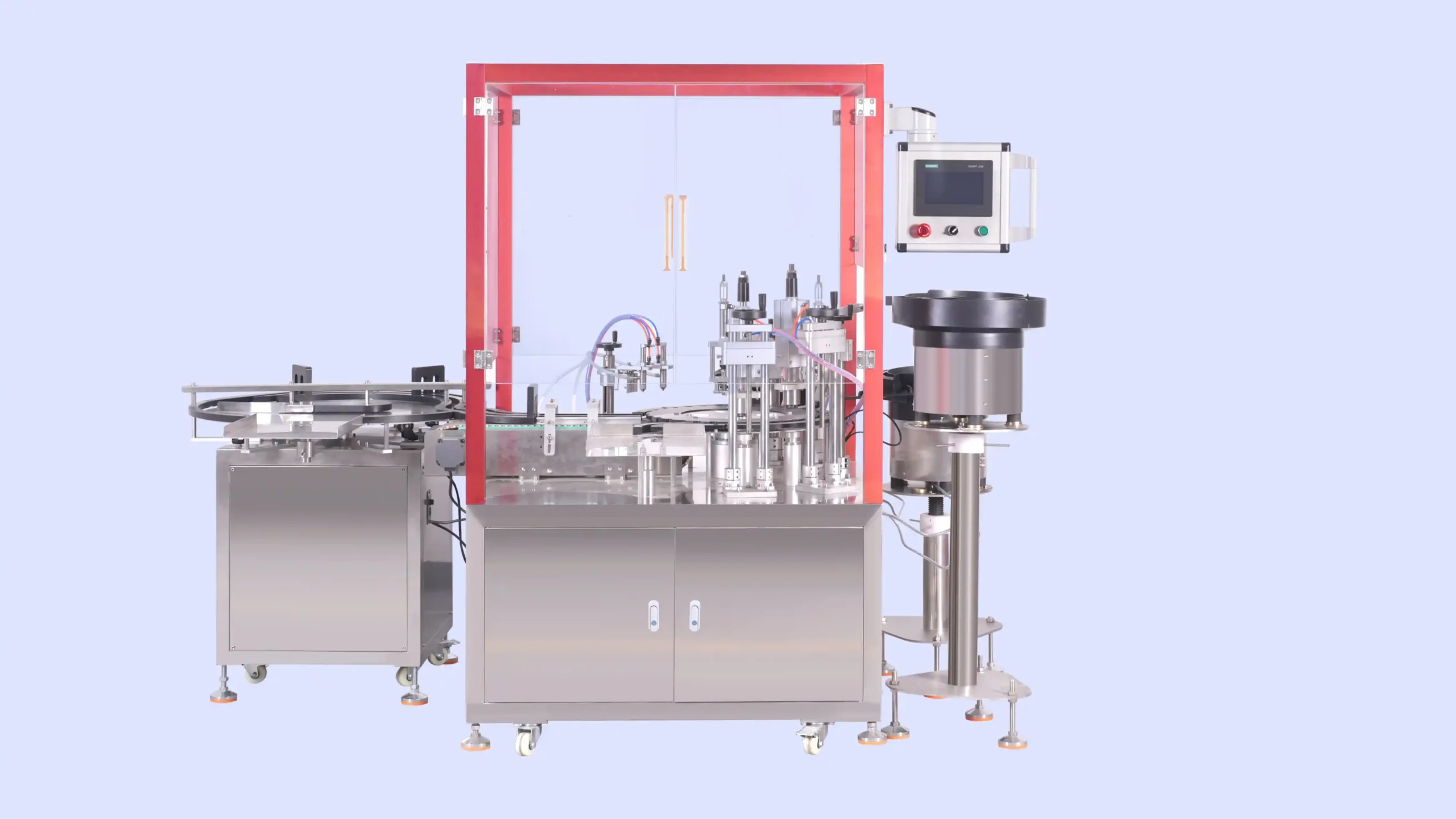
The 2-Head Vial Liquid Filling Machine combines independent servo-driven magnetic pumps with automatic rubber stoppering, cap placing, and aluminum-cap crimping. A rotary bottle unscrambler organizes manually loaded glass vials, while included conveying and collection equipment handles their movement through the line. The system serves manufacturers packaging compatible low-viscosity pharmaceutical liquids, cosmetic preparations, and essential oils in small-volume stoppered vials.
| Integrated Functions | Bottle Feeding / Bottle Discharge / Collection Table / Automatic Filling / Stopper/Dropper/Inner Plug Inserting / Stopper/Dropper/Inner Plug Pressing / Cap Feeding / Cap Placement / Crimping | Machine Frame Material | SUS304 Stainless Steel Frame |
| Filling Principle | Magnetic Pump | Conveyor System | Conveyor Optional (POM Slat Chain, SUS304 Chain, PVC/PU Flat Belt) |
| Output Configuration | 2-out | Motor Brand | Top-Tier Chinese Servo (Inovance / Equivalent) |
| Machine Layout Type | Rotary Filling Machine | Servo Drive Type | Servo-driven Filling Pump Motor / Servo-driven Conveyor Belt Motor |
| Container Type | Vial+ Stopper + Aluminum Cap/Flip-Off Cap | Photoelectric Brand | Panasonic |
| Container Material | Glass / Aluminum | Pneumatic Components Brand | AirTAC |
| Filling Volume Range (ml) | 1ml~10ml | Cylinder Brand | Airtac |
| Filling Accuracy | ±0.5% | fill_electrical_components | Schneider / Siemens / Omron (Optional/Customizable) |
| Filling Head/Heads | 2 | Voltage | Configurable to local grid (110V–480V, 50/60Hz, Single or 3-Phase) |
| Nozzle Type | Standard Direct Flow Nozzles | Total Power (kW) | 2 |
| Drip Prevention | Pneumatic Anti-Drip Mechanism Included | Air Pressure | 0.4–0.8 MPa |
| Production Speed (Bottles Per Minute) | 80-100 | Drive Type | Electro-Pneumatic Combined |
| Bottle / Container Diameter (mm) | Φ16~Φ22 | Installation Type | Mobile (Caster-Mounted) |
| Bottle / Container Height (mm) | 20~60 | Automation Level | Fully Automatic |
| Feeding Method | Self-priming | Control System | PLC + HMI Touch Screen Control |
| Bottle Handling Method | Rotary Turntable | PLC System | Siemens |
| With Machine Cover | Yes | HMI / Touch Screen | Siemens |
| Capping Type | Press-on / Snap Capping / ROPP Capping (Aluminum Roll-on) | Machine Dimensions(L*W*H)mm | 1873×1480×2033 |
| Material Contact Parts | SUS316L Stainless Steel (Pharmaceutical Grade) | Machine Weight (kg) | 300 |
Product Video
Product Overview
StriversMachinery’s automatic two-head vial filler coordinates liquid dosing and closure assembly within one production arrangement. Operators supply empty glass vials to the rotary infeed table and replenish liquid, rubber stoppers, and caps. The machine then handles container feeding, filling, stopper insertion and pressing, cap placing, crimping, and finished-vial collection.
Each filling head has an independently servo-driven magnetic pump. This arrangement allows the delivered quantity from each outlet to be checked and adjusted during setup. Applications focus on compatible low-viscosity liquids rather than thick creams, gels, or particle-containing formulations.
The selected package consists of a glass vial, rubber stopper, and aluminum or flip-off cap. After filling, the stopper enters the vial opening, followed by cap placement and aluminum-skirt crimping. The closure sequence does not include screw capping, ROPP thread rolling, or dropper assembly.
Included transport and the collection turntable provide a defined route from manually supplied empty containers to finished output. Manufacturers can assess this configuration where the required vial-filling output exceeds the needs of a compact single-head arrangement.
The machine belongs within the vial filling and closure equipment range, with selection based on the actual liquid, complete package, and required operating conditions.
Machine Configuration
The standard system includes a rotary bottle unscrambler, two independently servo-driven magnetic filling pumps, automatic stopper feeding and insertion, cap feeding and placement, and an aluminum-cap crimping assembly. Connecting transport and a finished-vial collection turntable are included.
Siemens PLC and touchscreen controls coordinate the operating sequence. Panasonic photoelectric components and AirTAC pneumatic components support container and closure handling. Servo motors and other electrical components follow the agreed order specification.
The frame is SUS304 stainless steel, with specified SUS316L stainless steel product-contact metal components. Tubing, seals, and other nonmetallic contact parts require separate compatibility selection.
The machine enclosure surrounds the processing area. Operators replenish containers, liquid, stoppers, and caps while the equipment performs the automatic sequence. Filling-outlet selection is matched to the liquid and package without assigning an unverified nozzle-closing mechanism.
Key Features
- Two independent servo-driven magnetic pumps provide separate dosing control for each filling outlet.
- Rotary infeed organizes manually loaded glass vials for the automatic processing sequence.
- Automatic rubber stopper feeding and pressing reduce individual closure-handling tasks.
- Automatic cap placement prepares stoppered vials for aluminum-skirt crimping.
- Included conveying connects container feeding, liquid dosing, and successive closure operations.
- The finished-vial collection turntable provides an organized discharge point for operators.
- Siemens PLC and touchscreen controls centralize routine machine operation and setup.
- Matched handling and closure tooling supports assessment of the complete vial package.
Applications
- Cosmetic Cream & Lotion, and Skin Care
- Pharmaceutical & Ointment Products
Recommended Machines
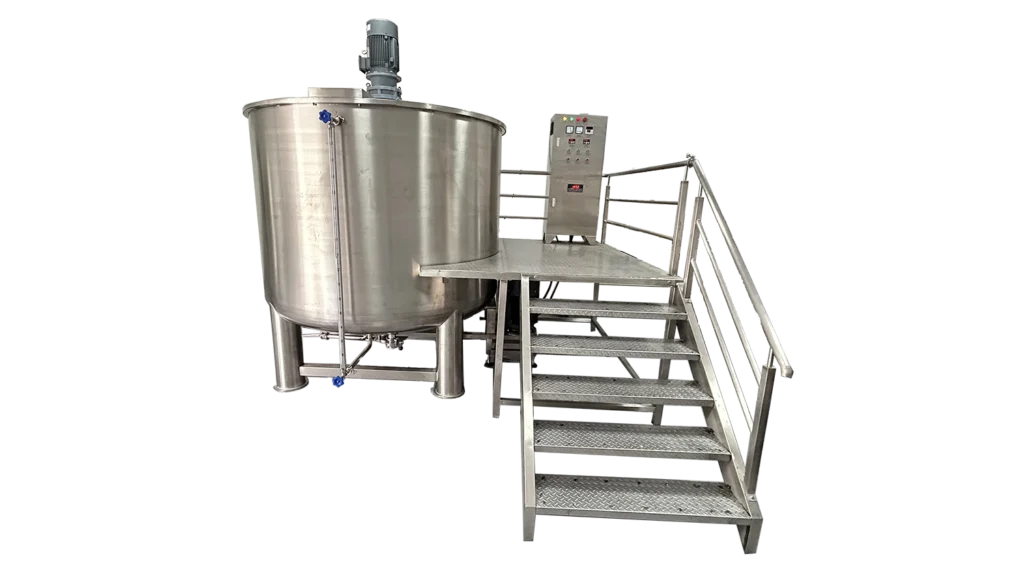
5000L Single Layer Homogenizer Mixing Tank for Liquid Soap, Detergent, Shampoo & Cosmetic Batch Production
View Details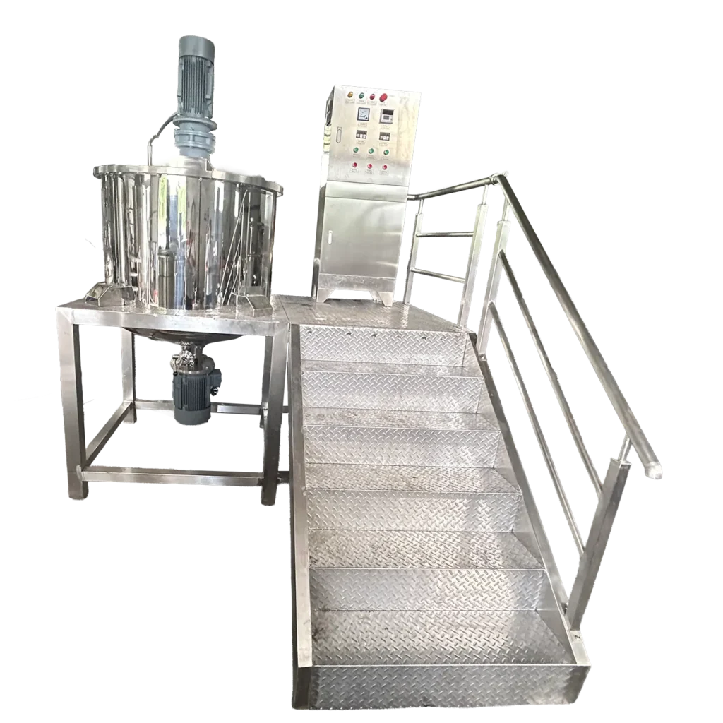
500L Semi-Open Liquid Soap & Shampoo Making Machine with Bottom Water-Cooled Homogenizer & Operation Platform
View Details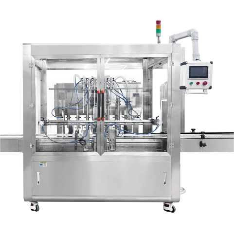

Working Principle
The two-head vial liquid filler advances glass vials through a coordinated dosing and closure sequence. Liquid metering is performed by two independent servo-driven magnetic pumps, while separate mechanisms handle containers, rubber stoppers, and caps.
- Manual loading and rotary infeed: Operators place empty vials on the rotary bottle unscrambler. The table organizes containers for transfer into the processing sequence.
- Container presentation: The handling system positions vials at the filling stations so their openings align with the liquid outlets.
- Liquid dosing: Each servo-driven magnetic pump delivers the selected quantity through its product pathway. Pump settings are established and checked using the intended liquid and target dose.
- Rubber stoppering: The automatic feeding arrangement presents stoppers for insertion and pressing into the filled vial openings.
- Cap placing: Aluminum caps or compatible flip-off caps are supplied and positioned over the stoppered vials.
- Crimping: The closing assembly forms the aluminum skirt around the vial neck to retain the closure components.
- Finished collection: Completed containers move through the included discharge transport to the collection turntable.
The PLC coordinates the operating sequence through the touchscreen interface. Operators maintain material supplies and carry out the required production checks. Liquid preparation, package preparation, environmental controls, and finished-product release remain part of the wider manufacturing process.
Optional Upgrades & Configurations
Custom Requirements
Corrosive-Resistant Construction for Strong Acids & Alkalis
Explosion-Proof Filling Systems for Flammable & Hazardous Environments
Custom Machine Layouts & Space-Saving Footprint Constraints
Extended & Custom-Length Long-Distance Conveyor Systems
Designated electrical component brands (Siemens PLC, Festo Pneumatics, etc.)
Irregular Bottle Shapes & Custom Packaging Solutions
Suitable Products
| Warranty | 24 Months | Payment Terms | 40% T/T Deposit, 60% Balance Before Shipment (Alibaba Trade Assurance Available) |
| Lead Time | 15–20 Working Days | Packaging | Standard Export Fumigation-Free Wooden Case |
After-Sales & Technical Support
🔧 Common Problems
Possible operating symptoms include irregular vial movement from the rotary infeed, uneven presentation at the filling outlets, or containers hesitating between stations. Filled quantities may differ between the two heads or vary during a run. Visible bubbles, droplets at the outlets, or wet vial rims may appear during filling. Rubber stoppers may arrive inconsistently, sit at an angle, or remain above the intended seating position. Caps may be absent, tilted, or unevenly positioned before crimping. Finished aluminum skirts may show uneven forming or loose retention. Other symptoms include abnormal operating noise, inconsistent pneumatic movement, interrupted discharge, or accumulation on the collection turntable.
🛠 Troubleshooting
Problem: Filled quantities differ between the two heads. Possible Cause: Different dosing settings, air in one pathway, or unequal supply conditions. Recommended Solution: Check samples from each outlet separately and inspect the product paths before adjusting the dosing setup.Problem: Quantity varies during production. Possible Cause: Changing liquid condition, an interrupted supply, or air entering a connection. Recommended Solution: Review the liquid supply and accessible connections before repeating the agreed quantity test.Problem: Droplets or wet rims appear after filling. Possible Cause: Outlet residue, unsuitable operating settings, or liquid discharge behavior. Recommended Solution: Inspect and clean the filling outlet before reviewing the setup with the actual liquid.Problem: Vials stop out of alignment. Possible Cause: Incorrect guide adjustment, debris, or package dimensions differing from the approved samples. Recommended Solution: Inspect the affected transfer position after safe isolation before adjusting container guides.Problem: Stoppers or caps seat unevenly. Possible Cause: Poor component presentation, mismatched packaging, or an unsuitable station adjustment. Recommended Solution: Inspect the complete vial and closure combination before reviewing insertion or cap-placement settings.Problem: The crimp is uneven or collection becomes congested. Possible Cause: Incorrect cap seating, tooling mismatch, or restricted finished-vial movement. Recommended Solution: Inspect the affected stage and clear the handling restriction under the operating procedure before component replacement.
🧼 Cleaning Method
1. Stop the machine according to the operating procedure. 2. Remove remaining vials, stoppers, and caps from the processing area. 3. Recover residual liquid using the approved product-handling method. 4. Isolate the electrical supply under the maintenance instructions. 5. Isolate the compressed-air supply according to the equipment procedure. 6. Relieve retained pressure before accessing affected components. 7. Remove accessible product-contact components according to the machine instructions. 8. Clean each pump pathway using a method permitted by the installed pump instructions. 9. Clean product tubing and connections with a compatible approved method. 10. Clean accessible filling-outlet components according to their service instructions. 11. Rinse reusable contact components where required by the cleaning procedure. 12. Clean vial guides and accessible stopper and cap handling surfaces. 13. Wipe the infeed and collection tables with suitable non-damaging materials. 14. Inspect cleaned parts for retained liquid or cleaning residues. 15. Dry reusable components using the established production procedure. 16. Reassemble removed parts according to the equipment instructions. 17. Record cleaning completion according to the facility’s requirements.
📋 Maintenance
1. Inspect both filling pathways for leakage or visible deterioration. 2. Examine accessible pump connections for loosening. 3. Check filling outlets for residue or damage. 4. Inspect rotary infeed guides for wear affecting vial presentation. 5. Examine vial-positioning parts for damage or loose attachments. 6. Check stopper feed guides and insertion tooling for buildup or wear. 7. Inspect cap guides for damage or misalignment. 8. Examine crimping tooling for residue or uneven wear. 9. Check pneumatic tubing and fittings for leakage or abrasion. 10. Inspect photoelectric sensing surfaces for contamination or displacement. 11. Check connecting transport for abnormal tracking or obstruction. 12. Examine the collection turntable for damage or unstable movement. 13. Inspect accessible frame fasteners and the securing arrangement. 14. Keep motor and drive ventilation areas clear. 15. Review electrical connections through qualified maintenance personnel. 16. Apply lubrication only where specified in the installed component instructions. 17. Verify filling and closure performance after relevant maintenance. 18. Record inspections, adjustments, and replacements in the maintenance log.
⚙️ Installation
1. Position the machine on a firm, level floor. 2. Establish access for vial loading, liquid supply, closure replenishment, and servicing. 3. Secure the mobile frame according to the installation instructions. 4. Inspect handling and closure components for transport damage. 5. Connect protective earthing through qualified electrical personnel. 6. Connect the electrical supply specified for the ordered configuration. 7. Connect compressed air within the required 0.4–0.8 MPa range. 8. Assemble the product pathways according to the equipment instructions. 9. Fit handling parts matched to the approved vial. 10. Install stopper and cap tooling matched to the complete package. 11. Align the filling outlets with the presented vial openings. 12. Check empty-vial transfer under the commissioning procedure. 13. Introduce representative liquid according to the approved handling method. 14. Adjust each filling head using the target dose. 15. Verify filled quantity separately for each outlet. 16. Assess stopper seating and finished crimp quality. 17. Check transfer to the collection turntable. 18. Document the accepted setup before routine production.
🔩 Spare Parts
Why Choose This Machine
- Separate dosing adjustment: Independent pump drives allow each filling outlet to be assessed and adjusted individually, helping identify differences that a combined average could conceal.
- Coordinated closure assembly: Filling, rubber stoppering, cap placing, and crimping share one production sequence, reducing manual transfer of open filled vials between separate machines.
- Defined container-handling scope: Rotary infeed, connecting transport, and collection are included, giving the installation a clear starting and finishing point.
- Focused low-viscosity application: The configuration concentrates on compatible liquid formulations, allowing product-path selection and performance assessment to follow the actual filling duty.
- Reduced individual component placement: Automatic stopper and cap feeding shift the operator’s task toward replenishment, supervision, and quality checks.
- Package-specific closing: Aluminum-skirt crimping matches the selected stoppered-vial format rather than combining unrelated closing methods under a general capping description.
- Centralized operation: The PLC and touchscreen bring routine settings and machine operation to one interface, supporting an orderly setup process.
Frequently Asked Questions
Installation Requirements
Provide an electrical supply matched to the ordered voltage, frequency, and phase configuration. The listed total power is 2 kW. Electrical connection and protective earthing must follow the machine wiring requirements and applicable installation rules.
Provide compressed air at 0.4–0.8 MPa with quality appropriate to the installed pneumatic components. Route cables, air lines, and product tubing away from moving handling parts and operator access routes.
Position the liquid supply to suit the final pump and product-path arrangement. Establish suitable storage and replenishment practices for vials, rubber stoppers, and caps.
The surrounding environment must suit the intended formulation and manufacturing process. Essential-oil and other chemically demanding applications require review of material compatibility, ventilation, and relevant site protection requirements. The enclosure does not establish a particular cleanroom classification.
Related Articles



Technical Buyer's Handbook & Deep Insight
Ready to Get a Quote?
Contact our team directly for pricing, customization options, and delivery timelines.
💬 WhatsApp Us NowGet Your Download Link
Please fill in your details and we'll send the download link to your email.