
Automatic Desktop Vial Liquid Filling Stoppering and Crimping Machine with Laminar Flow Hood for Pharmaceutical & Cosmetic Liquids

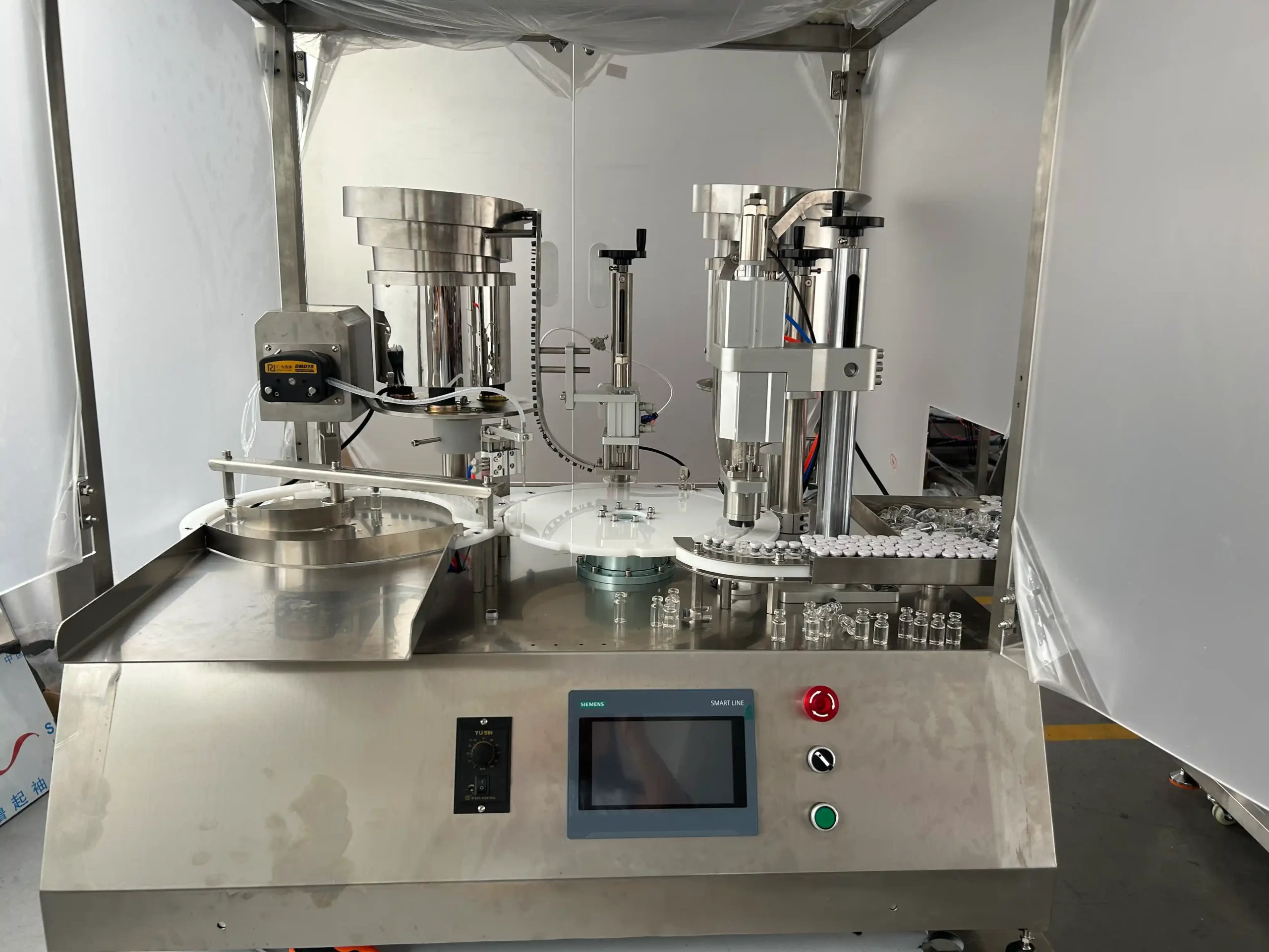
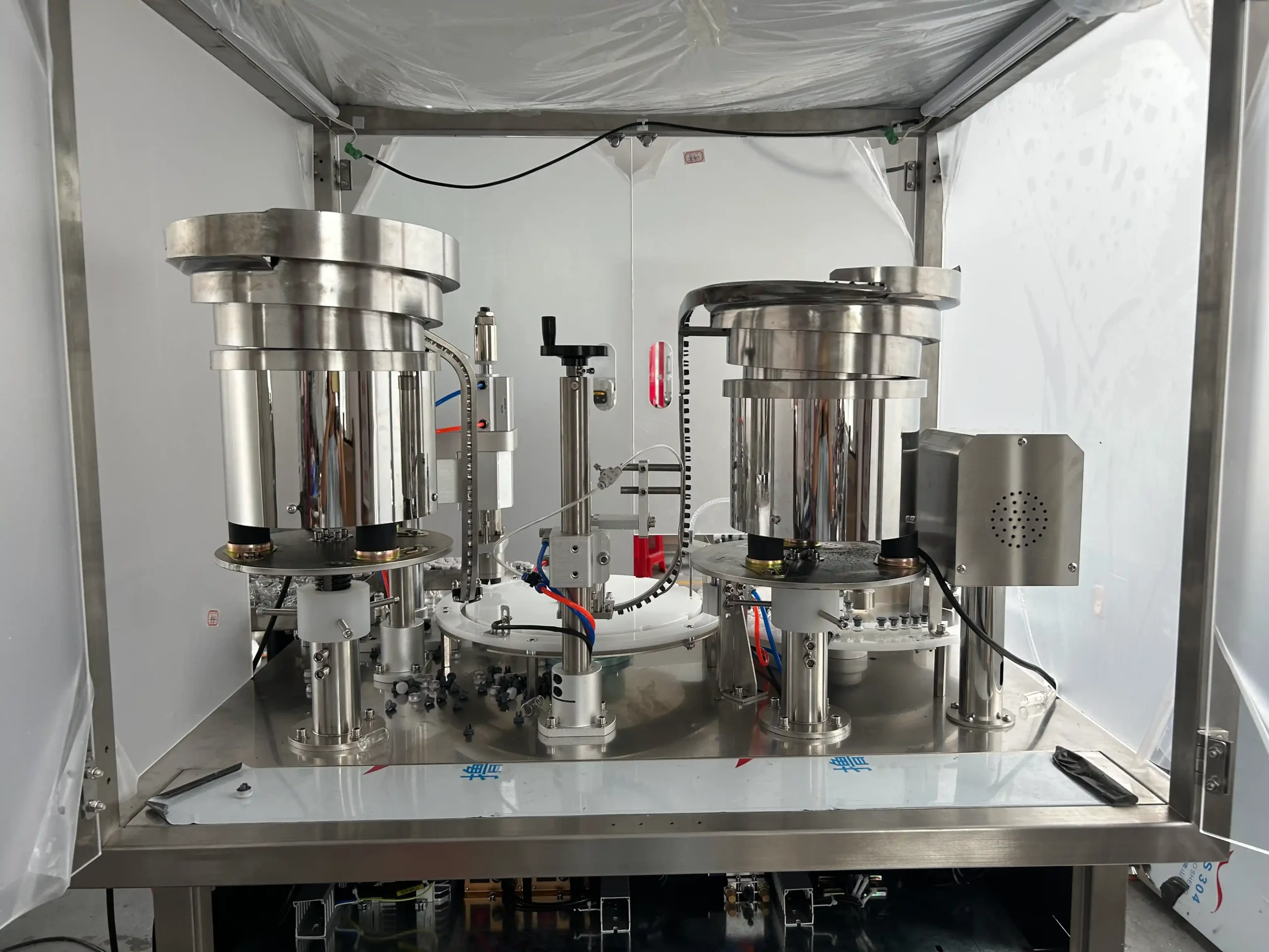
The Automatic Desktop Vial Filling Machine combines 1–10 mL peristaltic filling, rubber stoppering, cap placing, and aluminum cap crimping in a compact benchtop unit. Operators supply empty vials, stoppers, and caps, while the machine carries out the processing sequence automatically. A laminar flow hood provides local air filtration and protection for the operating area, supporting small-volume pharmaceutical, laboratory, and cosmetic liquid packaging.
| Integrated Functions | Bottle Feeding / Rotary Indexing / Collection Table / Stopper/Dropper/Inner Plug Inserting / Stopper/Dropper/Inner Plug Pressing / Cap Feeding / Crimping | Machine Frame Material | SUS304 Stainless Steel Frame |
| Filling Principle | Peristaltic Pump | Conveyor System | Conveyor Optional (POM Slat Chain, SUS304 Chain, PVC/PU Flat Belt) |
| Output Configuration | 1-out | Motor Brand | Top-Tier Chinese Servo (Inovance / Equivalent) |
| Machine Layout Type | Rotary Filling Machine | Servo Drive Type | Servo-driven Filling Pump Motor / Servo-driven Conveyor Belt Motor |
| Container Type | Vial+ Stopper + Aluminum Cap/Flip-Off Cap | Servo Motor Brand | Inovance/XINJE/Leadshine |
| Container Material | Glass / Aluminum / Rubber | Photoelectric Brand | Panasonic |
| Filling Volume Range (ml) | 1-10 | Pneumatic Components Brand | AirTAC |
| Filling Accuracy | ≤±3% | fill_electrical_components | Schneider / ABB / Siemens / Omron / Fuji /Mitsubishi(Optional/Customizable) |
| Filling Head/Heads | 1 | Voltage | Configurable to local grid (110V–480V, 50/60Hz, Single or 3-Phase) |
| Nozzle Type | Pneumatic Shut-off Nozzles (Anti-Drip) | Total Power (kW) | 2 |
| Drip Prevention | Pneumatic Anti-Drip Mechanism Included | Air Pressure | 0.4–0.8 MPa |
| Production Speed (Bottles Per Minute) | 40 | Drive Type | Electro-Pneumatic Combined |
| Bottle / Container Diameter (mm) | Φ16~Φ22 | Installation Type | Benchtop |
| Bottle / Container Height (mm) | 20~60 | Automation Level | Fully Automatic |
| Feeding Method | Self-priming | Control System | PLC + HMI Touch Screen Control |
| Bottle Handling Method | Rotary Turntable | PLC System | Siemens |
| With Machine Cover | Yes | HMI / Touch Screen | Siemens |
| Capping Type | Press-on / Snap Capping / ROPP Capping (Aluminum Roll-on) | Machine Dimensions(L*W*H)mm | 1521×970×1000 |
| Material Contact Parts | SUS316L Stainless Steel (Pharmaceutical Grade) | Machine Weight (kg) | 100 |
Product Gallery

Product Video
Product Overview
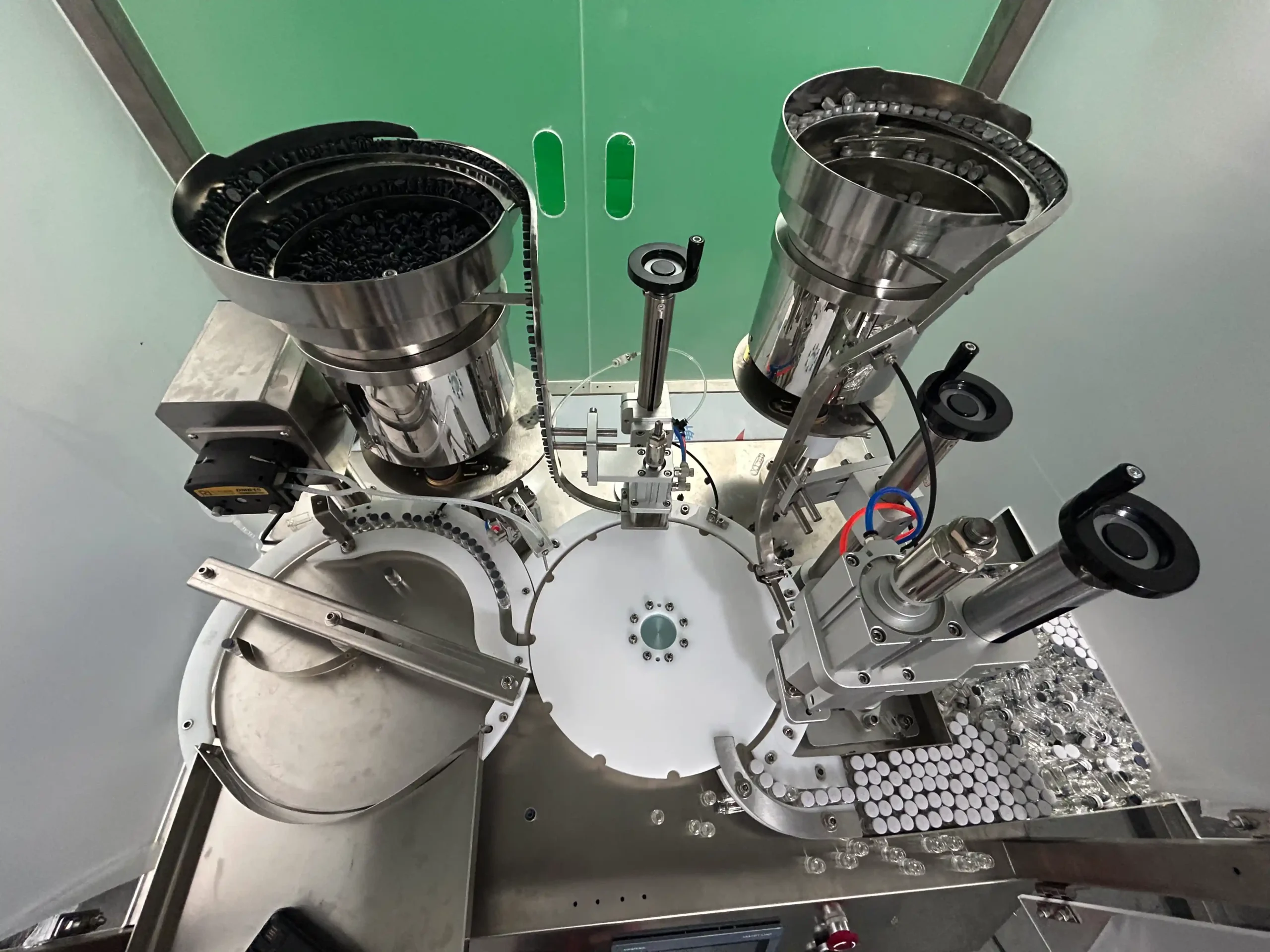
StriversMachinery’s JJ-01S brings small-volume vial filling and closure assembly onto one desktop platform. A single filling head handles 1–10 mL doses, followed by automatic rubber stoppering, cap placing, and pneumatic crimping. Finished vials discharge to the collection area without manual transfer between these operations.
The standard container range covers vial diameters of 16–22 mm and heights of 20–60 mm. Bottle guides, rotary positioning parts, stopper feeding components, and crimping tooling are matched to the selected vial and closure combination. Aluminum caps and flip-off caps are secured by crimping their aluminum skirts around the vial neck.
With a rated output of 40 bottles per minute, the equipment serves manufacturers packaging compatible pharmaceutical liquids, diagnostic reagents, laboratory solutions, and cosmetic liquids in small vials. Actual operating output depends on dose size, liquid behavior, packaging consistency, and material replenishment.
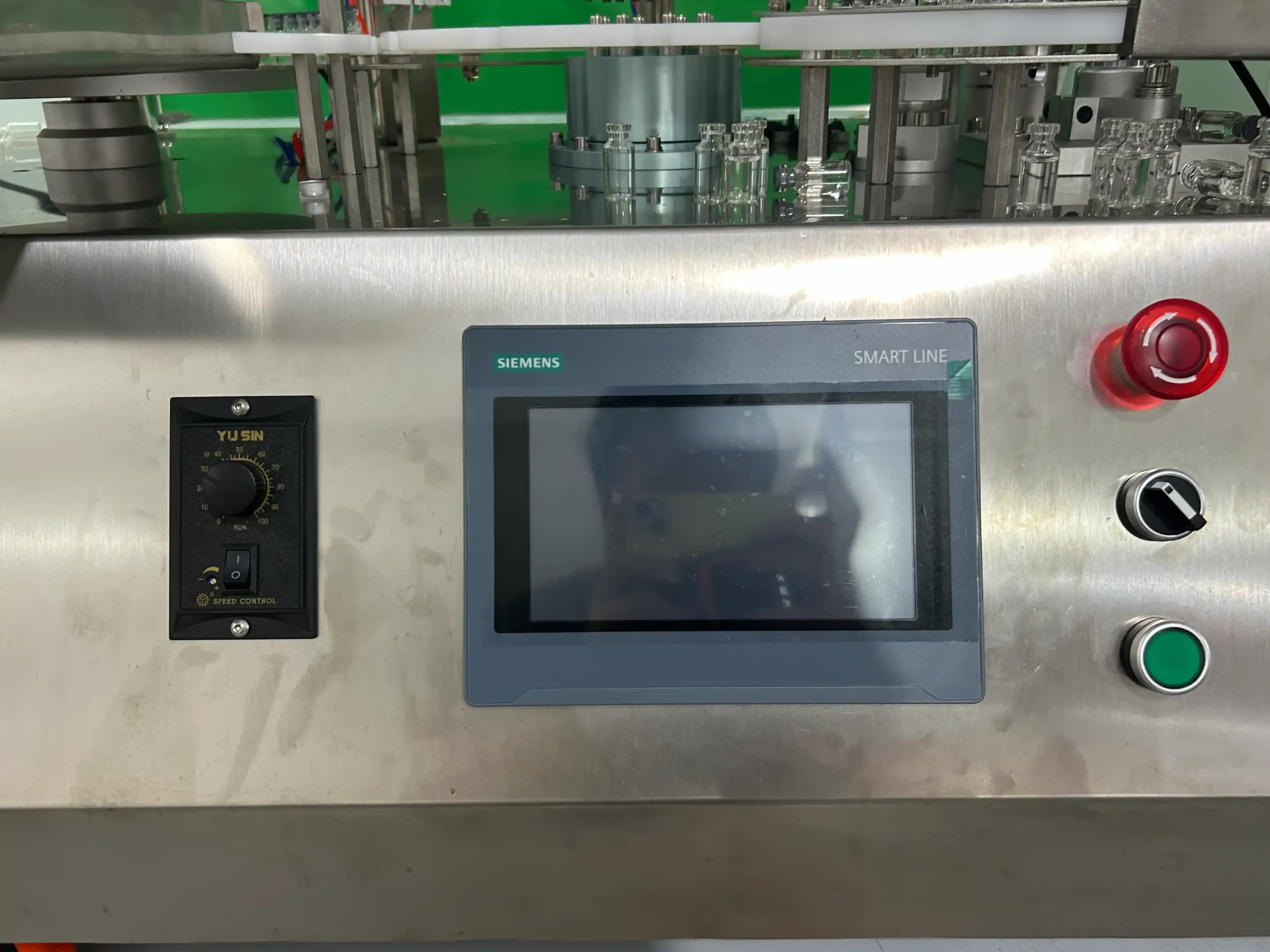
The enclosed working area incorporates a laminar flow hood for local air filtration and operating-area protection. Siemens PLC and touchscreen controls coordinate the process, while the 1521 × 970 × 1000 mm structure keeps the filling and closure stations together. Explore the wider vial filling, stoppering and capping equipment range for related packaging requirements.
Machine Configuration
The JJ-01S uses a single-head peristaltic filling system with servo-driven dosing and a cylinder-operated filling-head lift. A servo indexing mechanism positions vials through the filling, stoppering, cap placing, and crimping stations.
- Automatic vial infeed following manual loading of empty containers.
- Automatic rubber stopper feeding and insertion.
- Automatic aluminum or flip-off cap feeding and placing.
- Pneumatic crimping assembly with tooling matched to the closure.
- Finished-vial discharge and collection area.
- Laminar flow hood and working-area enclosure.
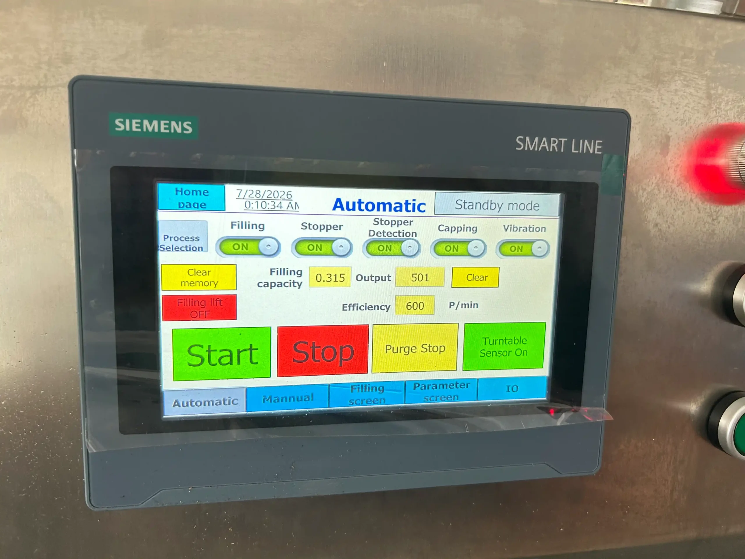
- Siemens PLC and HMI touchscreen control.
- Panasonic photoelectric components and AirTAC pneumatic components.
- SUS304 stainless steel frame.
The complete hood-equipped unit has a rated power of 2 kW and a net weight of 100 kg. Its documented supply is 220 V, 50 Hz, with compressed air at 0.6–0.8 MPa. Product-contact tubing and fittings are selected for the liquid and cleaning process.
Key Features
- Single-head peristaltic filling covers small liquid doses from 1 to 10 mL.
- Servo rotary indexing positions vials through the integrated processing stations.
- Automatic stopper feeding and insertion reduce handling of individual rubber closures.
- Automatic cap placing prepares each vial for pneumatic aluminum skirt crimping.
- Compatible aluminum and flip-off caps use closure-specific feeding and crimping tooling.
- Laminar flow hood provides local air filtration above the operating area.
- Siemens PLC and touchscreen provide centralized access to machine operating settings.
- Compact benchtop construction combines filling, closure assembly, and finished-vial collection.
Applications
- Cosmetic Cream & Lotion, and Skin Care
- Pharmaceutical & Ointment Products
Recommended Machines

Automatic 2-Head Vial Liquid Filling Capping Machine with Rotary Bottle Unscrambler for Pharmaceutical, Cosmetics & Essential Oils
View Details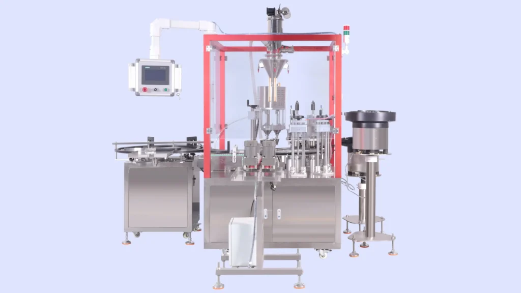
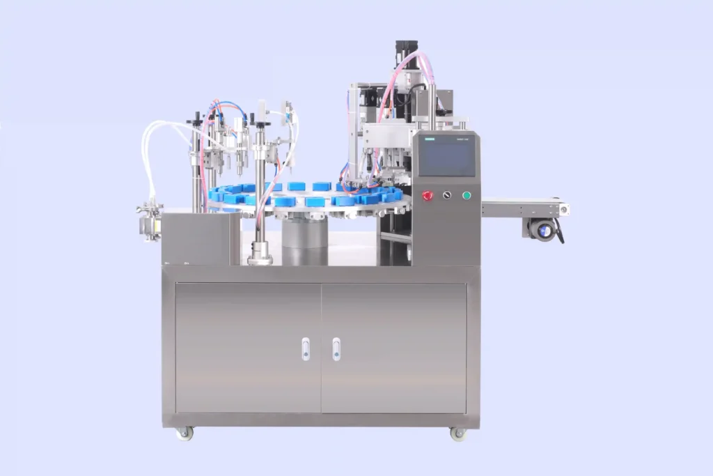
Automatic 2-Head Vial Powder Filling and Capping Machine with Rotary Infeed Table and Vacuum Powder Feeder for Pharmaceutical & Beauty Products
View Details
Working Principle
The desktop vial filling and crimping machine advances containers through a coordinated rotary sequence. Operators load empty vials into the infeed area and replenish the stopper and cap feeders during production.
- Vial infeed: The infeed mechanism transfers manually supplied empty vials toward the rotary positioning system.
- Rotary positioning: The servo indexing mechanism moves each vial to the required processing position, maintaining alignment between the container and station tooling.
- Liquid filling: The peristaltic pump meters liquid by progressively compressing flexible tubing. The servo-driven pump delivers the set dose through the filling outlet, while the cylinder-operated lift controls filling-head movement.
- Rubber stoppering: The feeding mechanism presents a stopper to the insertion station. The stopper is placed and pressed into the vial opening.
- Cap placing: An aluminum cap or flip-off cap is supplied to the stoppered vial and positioned over its neck.
- Crimping: The pneumatic crimping assembly forms the aluminum skirt around the vial neck to retain the closure assembly.
- Finished output: The rotary handling mechanism transfers completed vials toward the collection area.
The PLC coordinates station timing through the processing cycle. Above the working area, the hood provides local filtered-air protection. Product preparation, container preparation, and the required production-environment controls remain part of the wider manufacturing process.
Optional Upgrades & Configurations
Custom Requirements
Corrosive-Resistant Construction for Strong Acids & Alkalis
Explosion-Proof Filling Systems for Flammable & Hazardous Environments
Custom Machine Layouts & Space-Saving Footprint Constraints
Extended & Custom-Length Long-Distance Conveyor Systems
Designated electrical component brands (Siemens PLC, Festo Pneumatics, etc.)
Irregular Bottle Shapes & Custom Packaging Solutions
Suitable Products
| Warranty | 24 Months | Payment Terms | 40% T/T Deposit, 60% Balance Before Shipment (Alibaba Trade Assurance Available) |
| Lead Time | 15–20 Working Days | Packaging | Standard Export Fumigation-Free Wooden Case |
After-Sales & Technical Support
🔧 Common Problems
Possible operating symptoms include uneven liquid levels between filled vials, visible bubbles in the delivered liquid, droplets remaining at the filling outlet, or incomplete doses. Vials may hesitate at the infeed, sit unevenly in the rotary positioning parts, or fail to transfer smoothly to the collection area. Rubber stoppers may arrive inconsistently, sit at an angle, or remain above the intended insertion position. Caps may be absent, tilted, or poorly seated before crimping. Finished closures may show uneven aluminum skirts, loose retention, or visible deformation. Other symptoms include intermittent station movement, inconsistent pneumatic action, unusual operating noise, or a change in the hood’s indicated operating condition.
🛠 Troubleshooting
Problem: Filled quantities vary between consecutive vials. Possible Cause: Incorrect tubing installation, air entering the liquid pathway, or an unsuitable filling setting. Recommended Solution: Check tubing placement and connections first. Verify the selected dose using the actual liquid before readjusting pump settings.Problem: Liquid drips after the filling cycle. Possible Cause: Residue at the filling outlet, unsuitable shut-off timing, or wear in the outlet assembly. Recommended Solution: Inspect the outlet for residue and verify its operating sequence before assessing components for replacement.Problem: Vials hesitate or tilt during rotary transfer. Possible Cause: Misaligned guides, debris in the positioning area, or packaging that differs from the installed tooling. Recommended Solution: Inspect the affected transfer position with the machine safely isolated. Compare the vial dimensions with the approved package specification.Problem: Rubber stoppers are inserted unevenly. Possible Cause: Irregular stopper presentation, an unsuitable insertion setting, or a mismatch between stopper and vial. Recommended Solution: Check the stopper feed path and component samples before adjusting the insertion arrangement.Problem: Caps sit unevenly or the finished crimp is loose. Possible Cause: Poor cap seating, mismatched tooling, or an incorrect crimping adjustment. Recommended Solution: Inspect cap placement and the complete closure assembly before adjusting the crimping station with representative samples.Problem: Pneumatic movement becomes inconsistent. Possible Cause: Unstable air supply, leakage, or a restricted connection. Recommended Solution: Check the supply against the specified 0.6–0.8 MPa range and inspect accessible connections for leakage.
🧼 Cleaning Method
1. Remove remaining production materials from the machine before beginning the approved cleaning procedure.2. Isolate the electrical and compressed-air supplies before accessing processing components.3. Drain residual liquid from the product pathway using the established product-handling procedure.4. Remove accessible product-contact components according to the machine instructions.5. Clean reusable tubing and filling components with a method compatible with the product and component materials.6. Replace tubing designated for single-use service according to the production procedure.7. Rinse reusable product-contact components according to the approved cleaning method.8. Clean accessible vial-positioning and closure-feeding surfaces with appropriate non-damaging materials.9. Wipe the enclosure and external machine surfaces without flooding electrical or pneumatic assemblies.10. Inspect cleaned components for visible residue, damage, or retained liquid.11. Dry reusable components using the established production procedure.12. Reassemble the product pathway according to the machine instructions.13. Perform any required sanitization under the facility’s approved procedure.14. Check the assembled pathway before returning the machine to production.15. Record completion of the cleaning process according to the facility’s documentation requirements.
📋 Maintenance
1. Inspect pumping tubing for flattening, cracking, leakage, or other visible deterioration.2. Check the filling outlet for buildup, damage, or irregular shut-off movement.3. Inspect liquid-path connections for loosening or leakage.4. Examine vial-positioning parts for wear that could affect container support.5. Check stopper and cap feed paths for residue, damage, or loose fittings.6. Inspect the crimping tooling for contamination, damage, or uneven wear.7. Examine accessible pneumatic lines and connections for deterioration or leakage.8. Check the filling-head lift for smooth movement under the machine’s prescribed inspection procedure.9. Inspect photoelectric sensing surfaces for contamination or displacement.10. Examine accessible fasteners for loosening at scheduled maintenance checks.11. Check the hood and filtration assembly according to its maintenance instructions.12. Review electrical connections through qualified maintenance personnel.13. Apply lubrication only at the locations and with the materials specified in the machine instructions.14. Verify filling and closure performance after maintenance that affects processing settings.15. Record inspections, adjustments, and replaced components in the equipment maintenance log.
⚙️ Installation
1. Position the machine on a stable supporting surface appropriate for its dimensions and weight.2. Level the equipment according to the installation instructions.3. Establish access space for replenishment, enclosure opening, cleaning, and servicing.4. Connect the protective earth through qualified electrical personnel.5. Connect the specified 220 V, 50 Hz electrical supply according to the wiring instructions.6. Connect the compressed-air supply within the specified 0.6–0.8 MPa range.7. Fit the vial-positioning parts selected for the approved container.8. Install the stopper-feeding components matched to the selected rubber stopper.9. Install the cap-feeding and crimping tooling matched to the approved closure.10. Assemble the peristaltic product pathway according to the pump and machine instructions.11. Inspect the enclosure and hood assembly before operation.12. Run an empty-container trial under the commissioning procedure.13. Adjust the filling setup using the intended liquid and dose.14. Check stopper insertion and crimp quality using the complete packaging assembly.15. Establish the finished-vial collection arrangement.16. Release the equipment for production under the facility’s operating procedure.
🔩 Spare Parts
Why Choose This Machine
- Fewer transfers between operations: Filling, rubber stoppering, cap placing, and crimping share one platform, reducing the need to move open vials between separate machines.
- Practical small-dose configuration: The 1–10 mL range concentrates the equipment on small-volume vial packaging rather than broad bottle-filling applications.
- Coordinated vial positioning: Servo indexing presents containers to successive stations, helping maintain alignment throughout the filling and closure sequence.
- Reduced repetitive closure handling: Automatic stopper and cap feeding allow operators to replenish components in batches instead of placing every closure individually.
- Compact production arrangement: The benchtop structure keeps the main processing stations and collection area together where production space is limited.
- Accessible operating controls: Siemens PLC and touchscreen controls bring machine operation to one interface, supporting setup and routine production supervision.
- Protection around the working zone: The enclosure and filtered-air hood provide a defined operating area for small-vial processing, alongside the facility’s own environmental and handling procedures.
Frequently Asked Questions
Installation Requirements
The documented electrical supply is 220 V, 50 Hz, with a rated machine power of 2 kW. Electrical connection and protective earthing must follow the machine wiring requirements and local installation rules. Any alternative supply arrangement should be specified before manufacture.
Provide compressed air at 0.6–0.8 MPa through a supply suitable for the machine’s pneumatic components. Air quality must meet the equipment and production-process requirements.
Prepare the liquid supply location so the product pathway can be routed without kinks or interference with moving parts. Store empty vials, rubber stoppers, and caps in an arrangement that supports orderly replenishment.
The surrounding room, material preparation, and operating procedures must suit the intended product. Keep the hood’s air openings unobstructed and position the equipment away from activities that disrupt the protected working area.
Related Articles


Technical Buyer's Handbook & Deep Insight
Ready to Get a Quote?
Contact our team directly for pricing, customization options, and delivery timelines.
💬 WhatsApp Us NowGet Your Download Link
Please fill in your details and we'll send the download link to your email.