
Semi-Automatic 10-Head Rotary Vacuum Perfume Filling Machine for Fragrance, Essential Oil & Cologne Glass Bottles
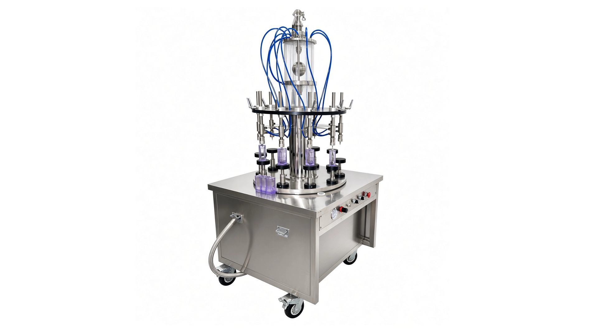
The 10-Head Rotary Vacuum Perfume Filling Machine is a semi-automatic, level-controlled filler for compatible glass bottles and low-viscosity fragrance liquids. Pneumatic rotation and vacuum generation support filling, while operators place and remove bottles manually. Within the liquid filling machines range, this configuration suits perfume packaging duties where bottle-mouth compatibility and a defined liquid level guide equipment selection.
| Filling Principle | Vacuum Negative Pressure Gravity Filling | Machine Frame Material | SUS304 Stainless Steel Frame |
| Machine Layout Type | Rotary Filling Machine | Motor Brand | Pneumatic Driven |
| Container Type | Bottles & Jars | Pneumatic Components Brand | AirTAC |
| Container Material | PET/HDPE/PP / Glass | Cylinder Brand | Airtac |
| Product Viscosity | Low Viscosity (Water, Toner, Alcohol) | Equipment Type | Perfume Filling Machine |
| Filling Volume Range (ml) | 5-1000 | Contact Material | Premium SUS316L stainless steel for all fluid contact zones |
| Filling Accuracy | ±0.5% | Explosion Proof | Explosion-Proof Configuration |
| Filling Head/Heads | 10 | Nozzle Type | Vacuum Anti-Drip Nozzle |
| Filling Nozzle Movement | Fixed Type | Voltage | Configurable to local grid (110V–480V, 50/60Hz, Single or 3-Phase) |
| Production Speed (Bottles Per Minute) | 20-50 | Air Pressure | 0.4–0.8 MPa |
| Bottle / Container Diameter (mm) | 5-90 | Installation Type | Mobile (Caster-Mounted) |
| Bottle / Container Height (mm) | ≤250mm | Automation Level | Semi-Automatic |
| Feeding Method | Self-priming | Machine Dimensions(L*W*H)mm | 1000*400*1800 |
| Bottle Handling Method | Manual | Machine Weight (kg) | 400 |
| Material Contact Parts | SUS316L Stainless Steel (Pharmaceutical Grade) | ||
Product Gallery


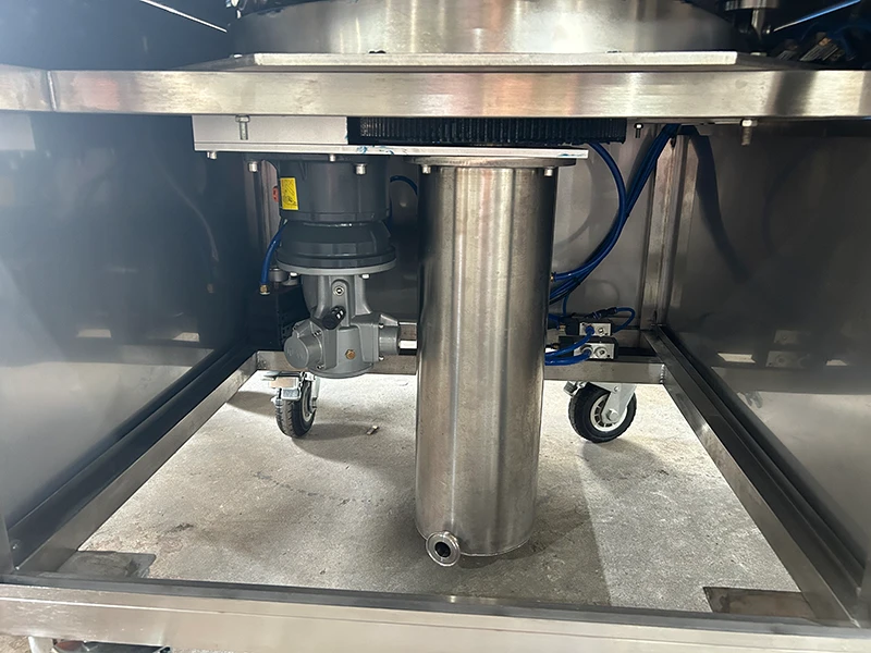
Product Overview
This semi-automatic rotary filler uses ten vacuum filling heads to fill compatible glass bottles to a preset liquid level. Operators load and unload bottles manually, while pneumatic power drives the rotary mechanism and vacuum generation.
The machine is intended for low-viscosity perfume, cologne and compatible fragrance liquids. Bottle selection considers the mouth geometry, nozzle fit and suitability for the negative-pressure filling process.
The 5–1000 mL application range accommodates different bottle formats, subject to the required setup. Filling ends at the selected liquid level rather than a programmed volumetric dose. Bottle geometry therefore remains important when evaluating the filled quantity.
The rotary arrangement provides multiple filling positions within an operator-assisted workflow. Actual output depends on the product, bottle format, filling level and loading and unloading sequence.
SUS316L stainless steel wetted components form part of the product pathway. The filler can be paired with separately selected pump-crimping and decorative collar-pressing equipment to suit the perfume package.
Machine Configuration
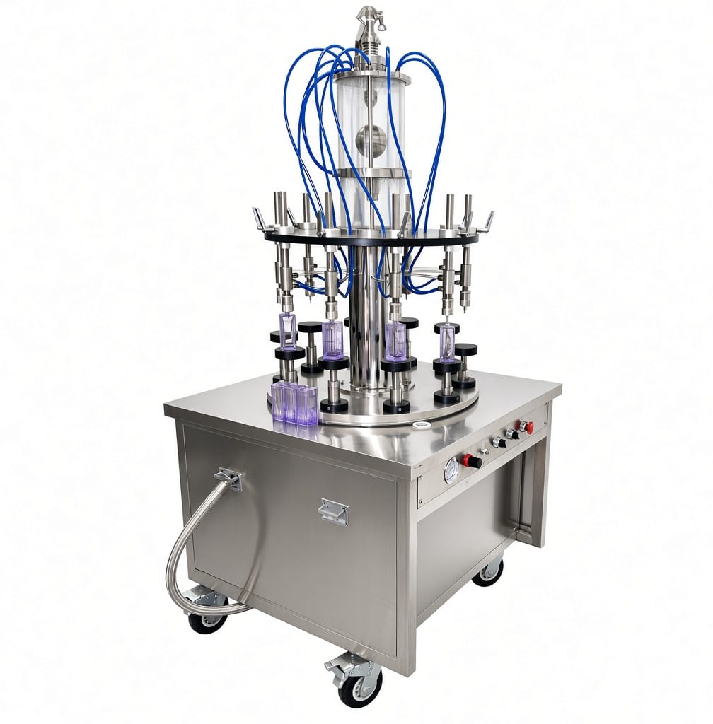
A SUS304 stainless steel frame supports the rotary filling assembly and ten fixed-type vacuum filling heads. Bottle placement and removal remain manual, with pneumatic power supplying the confirmed rotary movement and vacuum-generation functions.
The filling arrangement draws compatible liquid from the supply container and uses a defined liquid level as the endpoint. The bottle opening, nozzle interface and supplied adjustment arrangement must be matched to the intended package.
SUS316L is specified for the stainless steel wetted components. Flexible tubing, seals and other nonmetallic contact parts require separate material confirmation against the formulation and cleaning method.
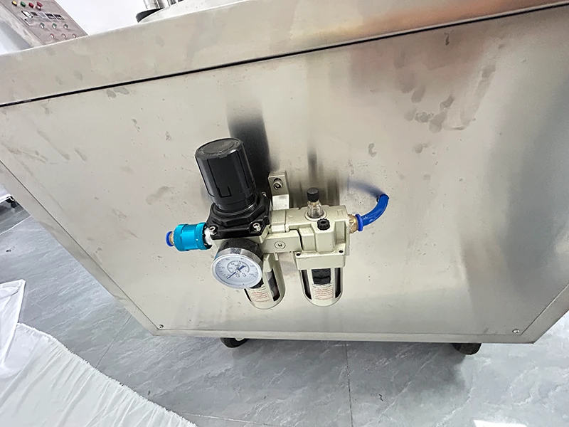
AirTAC pneumatic components and cylinders are listed in the supplied configuration. A caster-mounted base supports planned positioning. Product-feed tubing, vacuum connections and the operator’s working area should be reviewed together when defining the installation.
Key Features
- Ten filling heads provide multiple bottle positions within the rotary arrangement.
- Liquid-level control defines the endpoint without relying on programmed volumetric dosing.
- Pneumatic rotation supports the supplied semi-automatic bottle-filling sequence.
- Pneumatic vacuum generation provides the confirmed negative-pressure filling function.
- Manual bottle handling allows operator-assisted presentation to the filling heads.
- Fixed-type vacuum nozzles require bottle-specific positioning and mouth compatibility.
- SUS316L stainless steel wetted components support formulation-specific material assessment.
- Caster mounting supports planned relocation under the approved handling conditions.
Applications
- Cosmetic Cream & Lotion, and Skin Care
- Perfume & Fragrance Products
Recommended Machines
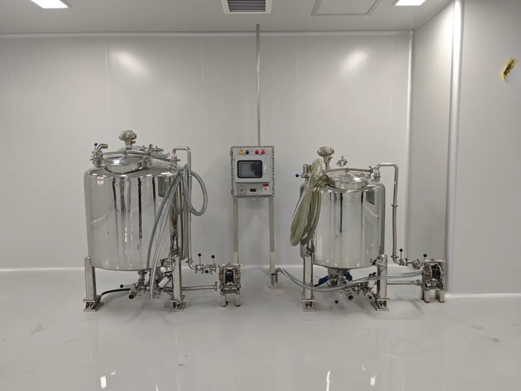

300L Perfume Making Machine with Chilling Freezing Filtration & Pneumatic Agitator for Eau de Toilette, Cologne & Essential Oil Processing
View Details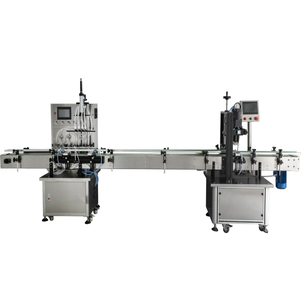

Working Principle
Operation begins with a compatible liquid supply and an approved glass-bottle format. The operator establishes the required filling level using the machine’s supplied adjustment method before routine production.
Compressed air powers the confirmed rotary mechanism and vacuum-generation arrangement. An operator places each bottle at the designated position so that its opening cooperates with the vacuum filling head.
The pressure difference draws low-viscosity liquid through the product pathway into the bottle. The filling endpoint is the selected liquid level, not a preset piston displacement or an assumed pump-delivered volume.
Once the level-controlled filling stage is complete, the bottle is removed according to the supplied operating sequence. The exact head arrangement and product-return or collection route should follow the machine documentation rather than be inferred from the general vacuum-filling principle.
The operator continues loading and unloading within the approved rotary sequence. Sustainable output depends on liquid behavior, bottle presentation, available compressed air and the manual handling task.
Filled bottles then proceed to the required closure operation. A compatible perfume bottle crimping machine can be assessed separately where the selected spray pump requires crimp attachment.
Changing bottles requires review of the nozzle interface, support position and filling level before production resumes. Equal liquid levels should not be treated as proof of equal delivered volume across bottles with different internal geometry.
Optional Upgrades & Configurations
Custom Requirements
Corrosive-Resistant Construction for Strong Acids & Alkalis
Explosion-Proof Filling Systems for Flammable & Hazardous Environments
Custom Machine Layouts & Space-Saving Footprint Constraints
Extended & Custom-Length Long-Distance Conveyor Systems
Designated electrical component brands (Siemens PLC, Festo Pneumatics, etc.)
Irregular Bottle Shapes & Custom Packaging Solutions
Suitable Products
| Warranty | 24 Months | Payment Terms | 40% T/T Deposit, 60% Balance Before Shipment (Alibaba Trade Assurance Available) |
| Lead Time | 15–20 Working Days | Packaging | Standard Export Fumigation-Free Wooden Case |
After-Sales & Technical Support
🔧 Common Problems
Possible observable symptoms include bottles finishing at different apparent liquid levels, one head filling more slowly than others, incomplete filling, intermittent liquid movement or visible air in the product tubing. Operators may notice leakage around the bottle-mouth interface, liquid trailing after bottle removal, product residue on the bottle neck or differences between repeated runs. Other observations may include weak vacuum indication where an indicator is supplied, audible air leakage, irregular rotary movement, bottle instability at a filling position or difficulty maintaining the intended loading and removal sequence. During changeover, retained fragrance or visible residue may remain in individual branches or nozzles. Filled bottles may also show acceptable visual levels while separate quantity checks fall outside the agreed criterion. These are potential operating observations rather than confirmed defects in the supplied machine.
🛠 Troubleshooting
Problem: One bottle finishes at a different liquid level. Possible Cause: Bottle geometry, positioning or the nozzle-level setup differs. Recommended Solution: Compare the bottle and approved head setting before adjusting the system.Problem: One filling head operates slowly or intermittently. Possible Cause: A poorly seated bottle, restricted product branch or leakage affects that position. Recommended Solution: Review bottle presentation. Stop and isolate the machine before inspecting the affected pathway.Problem: Several heads lose filling performance together. Possible Cause: Product supply or pneumatic-service conditions differ from the approved arrangement. Recommended Solution: Compare available supply readings with the operating record before changing settings.Problem: Liquid trails from a nozzle after bottle removal. Possible Cause: Residue, a damaged sealing component or an unsuitable removal sequence affects closure. Recommended Solution: Follow the approved stop and isolation procedure before cleaning or inspecting the nozzle.Problem: Rotary movement becomes irregular. Possible Cause: An obstruction, unstable air supply or a pneumatic fault affects the drive. Recommended Solution: Stop the machine. Arrange qualified inspection before restarting.Problem: Visual levels are consistent but quantity checks vary. Possible Cause: Bottle internal geometry or the measurement conditions differ. Recommended Solution: Review the packaging samples and quantity-check method. Do not treat equal levels as proof of equal volume.
🧼 Cleaning Method
1. Remove the filler from production service under the approved shutdown procedure. 2. Recover remaining product through the designated product-handling route. 3. Isolate the machine’s energy sources according to the site lockout procedure. 4. Release retained pneumatic and vacuum energy through the approved method. 5. Prepare a designated receiver for cleaning liquids and recovered residue. 6. Disconnect the product supply where the component instructions require removal. 7. Remove designated detachable nozzle parts according to the service procedure. 8. Pre-rinse the product pathway with a compatible medium specified for the formulation. 9. Apply the approved cleaning method to each of the ten product branches. 10. Clean detachable product-contact components through their permitted access method. 11. Clean nozzle sealing surfaces without damaging the bottle-contact interface. 12. Rinse the product pathway until the specified acceptance criteria are satisfied. 13. Inspect accessible tubing and connections for retained residue. 14. Reassemble serviced components using the approved connection method. 15. Perform the designated post-cleaning leak and function checks. 16. Verify the required fragrance-changeover acceptance results before product release.
📋 Maintenance
1. Isolate the compressed-air supply before accessing moving or pressurized components. 2. Release retained pneumatic and vacuum energy through the approved procedure. 3. Inspect bottle-contact nozzle seals for wear or deformation. 4. Examine filling nozzles for residue or visible damage. 5. Inspect product tubing for deterioration, discoloration or chemical attack. 6. Check vacuum tubing for damage or loose connections. 7. Examine product connections for leakage or damaged sealing surfaces. 8. Inspect bottle supports for looseness or wear. 9. Check accessible rotary-mechanism attachments according to the service instructions. 10. Inspect pneumatic tubing and fittings for visible damage. 11. Check AirTAC cylinders and pneumatic components according to their component instructions. 12. Service installed air-treatment components according to their documentation. 13. Verify supplied pressure or vacuum indicators through the approved checking procedure. 14. Test supplied stop functions using the designated functional test method. 15. Inspect casters and restraints before returning the machine to operation. 16. Record service findings against the affected filling head or component.
⚙️ Installation
1. Review the approved general arrangement before preparing the operating area. 2. Verify the delivery route against the final transport dimensions and handling instructions. 3. Obtain approval of the floor for the confirmed operating load. 4. Inspect the delivered machine for visible transport damage. 5. Position the assembly using the designated handling method. 6. Secure the caster-mounted base at the approved operating location. 7. Confirm access for manual bottle placement and removal. 8. Position the product supply according to the approved suction arrangement. 9. Connect the product pathway using the specified compatible tubing and fittings. 10. Connect the regulated compressed-air supply according to the pneumatic schedule. 11. Verify the installation provisions required by the site assessment. 12. Prepare the approved cleaning and liquid-collection arrangement. 13. Perform the specified pre-use cleaning procedure. 14. Set up the approved glass-bottle format according to the machine instructions. 15. Adjust the intended filling level through the supplied method. 16. Verify the operating sequence using the approved commissioning medium. 17. Evaluate representative product and bottles against the agreed acceptance criteria. 18. Document the approved setup before routine production.
🔩 Spare Parts
Why Choose This Machine
- A level-oriented packaging approach: The filling endpoint follows the selected liquid level, making this configuration relevant where the bottle’s filled appearance forms part of the packaging requirement.
- Several available filling positions: The ten-head rotary arrangement provides multiple bottle positions without presenting the machine as an automatic bottle-feeding line.
- Defined pneumatic functions: Confirmed pneumatic rotation and vacuum generation establish a clear basis for specifying the compressed-air service.
- Operator-assisted packaging: Manual placement and removal can suit production arrangements where personnel remain responsible for bottle presentation and transfer.
- Separate closure selection: The filling station can be assessed alongside the actual pump-attachment method instead of assuming that every perfume bottle uses the same closure equipment.
- Format-specific evaluation: Reviewing the glass bottle, mouth interface and liquid level together provides a practical selection basis beyond nominal container capacity alone.
Frequently Asked Questions
Installation Requirements
The listed machine weight is 400 kg. Confirm its basis against the final equipment documentation before assessing floor loading and handling. Secure the caster-mounted base at the approved operating position.
Provide a compressed-air service matched to the final pneumatic schedule. The supplied operating-air range is 0.4–0.8 MPa. This is a pneumatic-service specification, not a bottle-pressure rating or a permitted product-vessel pressure. Air consumption and the required treatment arrangement need confirmation before compressor sizing.
Position the product supply and tubing according to the approved installation instructions. Do not infer an allowable suction lift or supply-container height from the self-priming description alone.
The manufacturer confirms an explosion-protection design, without ATEX or Ex certification. Review the complete installation, ventilation, ignition-source control and required bonding or earthing provisions through the applicable site assessment.
Provide designated arrangements for product recovery, cleaning liquids and waste collection. Confirm bottle supply and receiving positions so operators can work within the approved handling sequence.
Related Articles


Technical Buyer's Handbook & Deep Insight
Ready to Get a Quote?
Contact our team directly for pricing, customization options, and delivery timelines.
💬 WhatsApp Us NowGet Your Download Link
Please fill in your details and we'll send the download link to your email.