
200L Portable Sealed Pneumatic Mixing Tank for Perfume Production – Explosion Proof
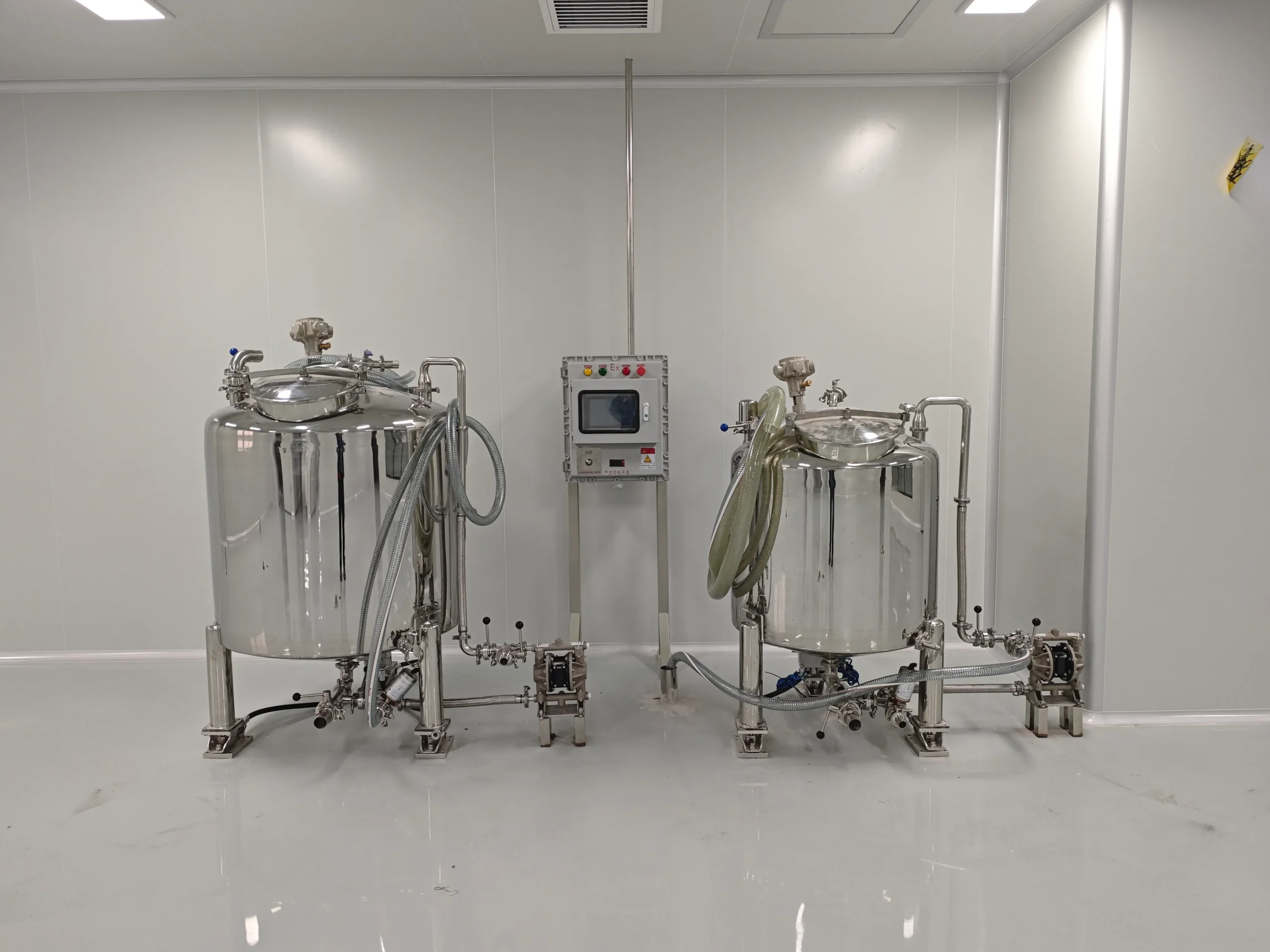
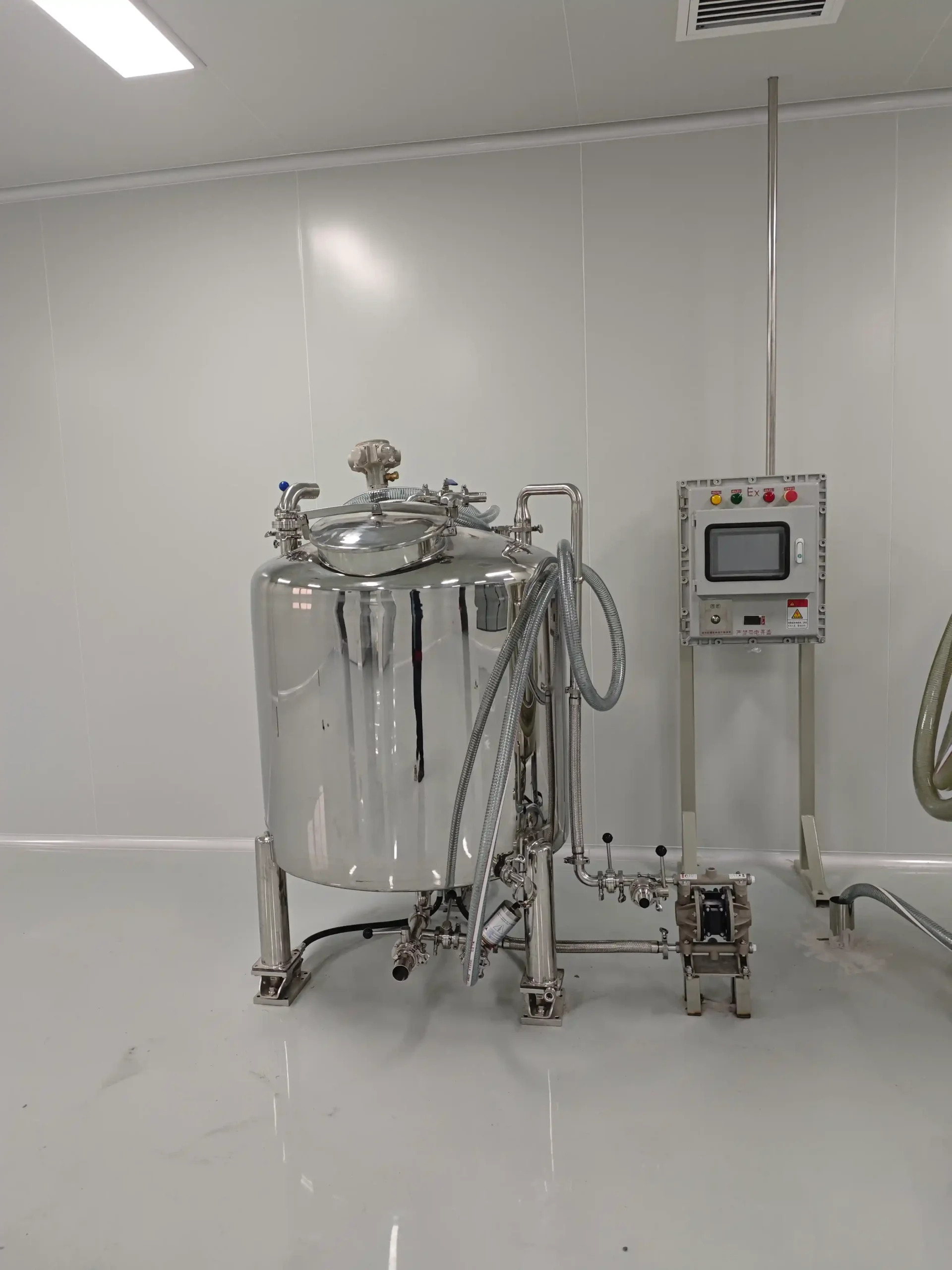
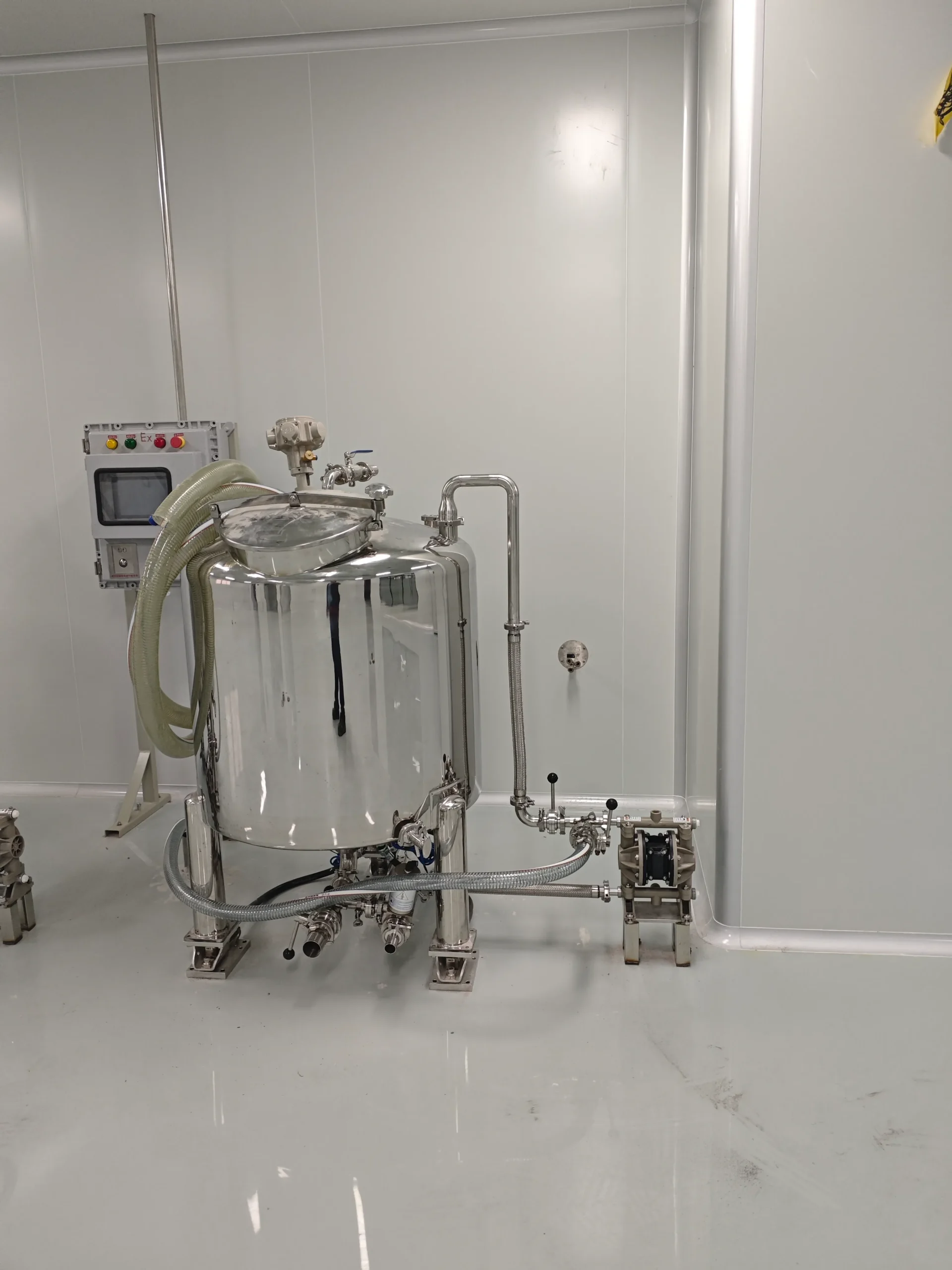
The 200L pneumatic perfume mixing tank provides a sealed vessel for compatible fragrance blending and formulation-defined maturation. Its mobile arrangement combines pneumatic agitation with a 200L batch capacity inside a 240L tank. PLC control or an agreed manual pneumatic configuration can support the operating method. Within the Perfume Production Equipment range, this model is a mixing and holding unit, without chilling or filtration.
| Equipment Type | Perfume Chilling & Filtration Machine (Perfume Making Machine) | Agitator Type | Propeller / High Shear Disperser (Equipped with Explosion-Proof Electric Motor for High-Velocity Fluid Uniformity) |
| perfume_automation_level | Semi-Automatic (Pneumatic Driven, Manual Bottle Feeding) | Air Pressure | 0.4–0.8 MPa |
| perfume_control_system | Manual Button Control | Drive Type | Pneumatic |
| Contact Material | Premium SUS316L stainless steel for all fluid contact zones | Installation Type | Mobile (Caster-Mounted) |
| Explosion Proof | Explosion-Proof Configuration / Advanced ATEX / Ex Explosion-Proof System | Automation Level | Fully Automatic |
| Production Capacity (L/Batch) | 200 | Control System | PLC + HMI Touch Screen Control |
| Tank Volume (L) | 240 | Machine Dimensions(L*W*H)mm | 750*750*1300 |
| Mixing Speed (rpm) | 0–120 rpm | Machine Weight (kg) | 150 |
| Aging Time | 24–48 Hours | ||
Product Gallery
Product Overview
This portable tank is intended for manufacturers who need a defined vessel for mixing and holding compatible perfume formulations. The sealed arrangement should be evaluated around ingredient charging, agitation, sampling, cleaning, and product transfer.
The supplied batch capacity is 200L within a 240L tank. SUS316L is specified for fluid-contact zones, and the listed agitation range is 0–120 rpm. The pneumatic drive provides the mixing action; no electric high-speed disperser is included.
PLC control is available for the agreed configuration. A manual pneumatic, semi-automatic arrangement can also be specified. These are control choices rather than evidence that every function or accessory is included together.
The equipment does not chill, freeze, or filter the perfume. It also does not establish a controlled maturation temperature or a universal holding period. Those conditions belong to the formulation and the wider production method.
Caster mounting supports repositioning under approved handling conditions. It does not establish permission to move the tank while operating, connected, full, or under pressure. The perfume and fragrance application page provides a separate resource for reviewing the wider process requirements.
Machine Configuration
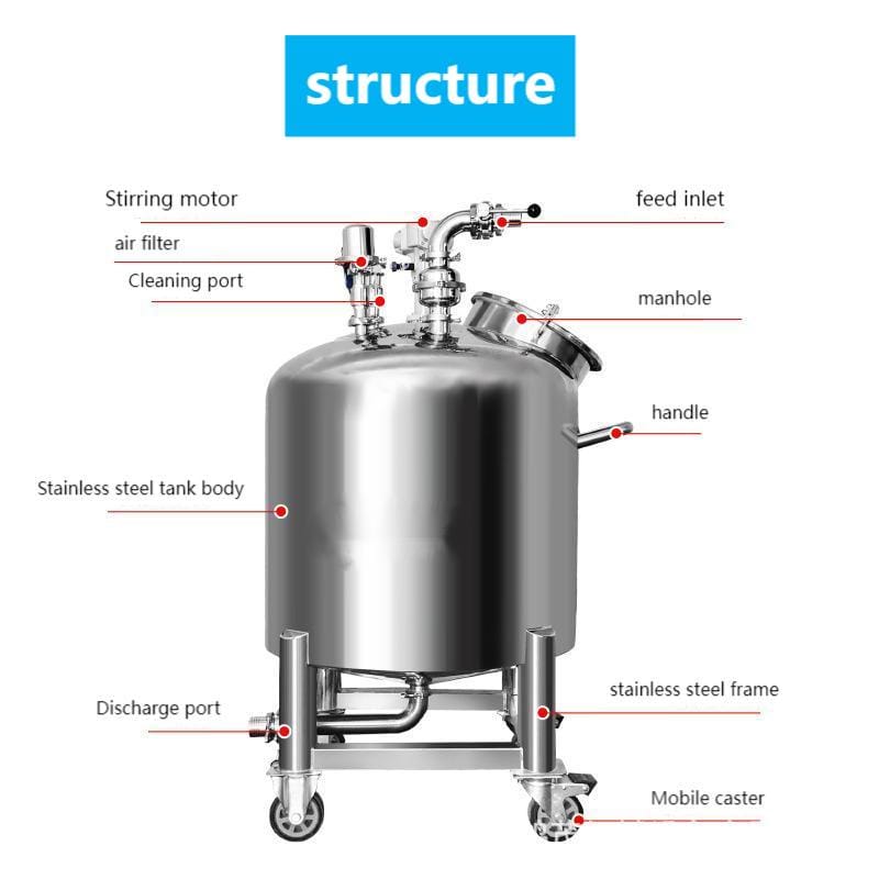
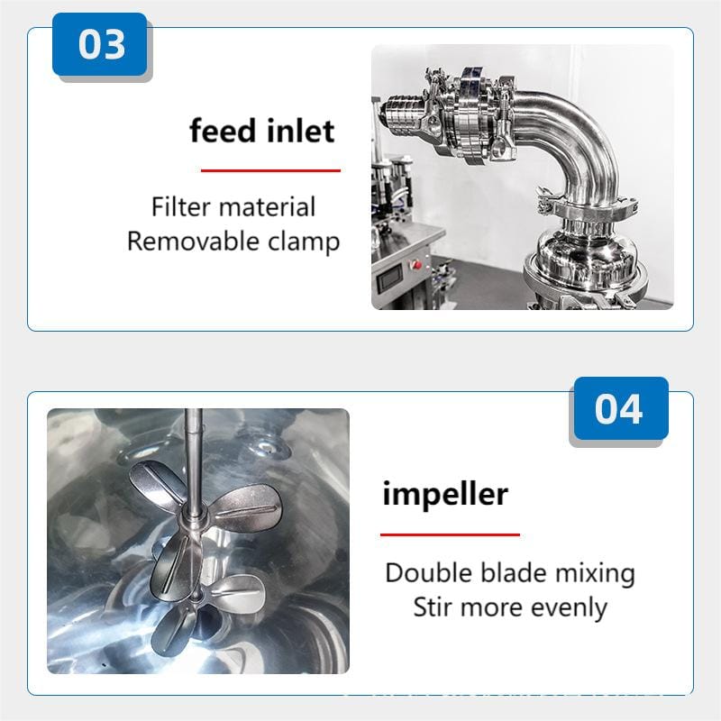
The equipment combines a sealed tank, pneumatic agitation assembly, selected controls, and a caster-mounted structure. SUS316L is specified for product-contact zones. The exact agitator geometry, shaft arrangement, lid closure, seals, and product connections should be identified in the approved drawing.
Compressed air supplies the agitation drive at the specified 0.4–0.8 MPa inlet range. Air consumption, required conditioning, and any lubrication requirements must follow the installed motor documentation. The compressed-air moisture control guide provides related utility context.
The PLC arrangement must be defined by its actual control functions. Manual pneumatic control is an alternative agreed configuration, not an assumed duplicate system.
No chilling unit, filter assembly, electric disperser, vacuum system, or pressure-assisted discharge arrangement is established for this tank. Electrical control components and their installation remain subject to the selected operating environment.
Key Features
- Sealed vessel arrangement supports compatible perfume mixing and formulation-defined holding.
- Pneumatic agitation provides the specified mixing drive without an electric disperser.
- Specified agitation range is 0–120 rpm under the approved operating conditions.
- SUS316L construction is specified for all fluid-contact zones.
- Two-hundred-liter batch capacity is provided within a 240L tank.
- PLC control can support the functions defined in the technical agreement.
- Manual pneumatic control is available as an agreed semi-automatic alternative.
- Caster-mounted structure supports repositioning under approved handling conditions.
Applications
- Cosmetic Cream & Lotion, and Skin Care
- Perfume & Fragrance Products
Working Principle
Ingredients are charged according to the approved perfume formulation. The tank closure, charging connections, and pressure-equalization arrangement must be used as defined in the supplied operating instructions.
Compressed air drives the agitator. Its operating setting is selected within the specified range to suit the formulation and batch conditions. The listed air pressure describes the pneumatic supply; it is not a pressure rating for the product chamber.
The PLC operates the functions included in the agreed configuration. Where manual pneumatic control is selected, the operator follows the defined batch sequence. Automatic weighing, ingredient dosing, electronic records, and complete recipe execution are not established by the supplied information.
Ingredient additions and mixing stages follow the formulation method. The fragrance and active-ingredient addition guide provides supporting context without defining one sequence for every perfume.
After mixing, the product can remain in the vessel for the formulation-defined holding period where the approved process permits it. Maturation time and environmental conditions require separate definition.
The batch is then sampled or transferred through the agreed handling arrangement. This machine does not perform chilling or filtration and does not establish vacuum or pressurized processing.
Optional Upgrades & Configurations
Suitable Products
| Warranty | 24 Months | Payment Terms | 40% T/T Deposit, 60% Balance Before Shipment (Alibaba Trade Assurance Available) |
| Lead Time | 15–20 Working Days | Packaging | Standard Export Fumigation-Free Wooden Case |
After-Sales & Technical Support
🔧 Common Problems
Potential symptoms include incomplete ingredient blending, inconsistent agitation speed, unexpected air leakage from the pneumatic system, excessive or changed exhaust noise, leakage around a closure or product connection, and differences between samples collected from the batch. Operators may also observe an unexpected control response, difficulty collecting or transferring product, residual fragrance after cleaning, or movement from the approved operating position. These are inspection topics rather than documented faults of this model. Record the batch quantity, formulation, agitation setting, supply conditions, and affected process stage before selecting corrective action. A difference in fragrance appearance or condition should not automatically be attributed to insufficient mixing. Formulation, ingredient condition, holding environment, and sampling method may also require review.
🛠 Troubleshooting
Problem: Ingredients do not blend as expected Possible Cause: Batch quantity, charging order, formulation behavior, or agitation setting differs from the approved method Recommended Solution: Compare the batch record with the agreed process and confirm effective agitator engagementProblem: Agitation speed becomes inconsistent Possible Cause: Air-supply conditions, pneumatic controls, exhaust restriction, or motor condition requires inspection Recommended Solution: Record the supply indication and operating condition, then follow the installed motor’s diagnostic procedureProblem: Air leakage or changed exhaust noise is observed Possible Cause: A pneumatic connection, hose, exhaust component, or motor component requires inspection Recommended Solution: Isolate and depressurize the pneumatic circuit before qualified inspectionProblem: A closure or product connection leaks Possible Cause: Seal condition, alignment, assembly, or material compatibility requires review Recommended Solution: Stop the affected operation and inspect the isolated connection according to the supplied procedureProblem: The PLC command does not produce the expected response Possible Cause: A required operating condition, control component, or pneumatic interface requires attention Recommended Solution: Record the command and any displayed indication, then follow the supplied control documentationProblem: Product transfer is slow or interrupted Possible Cause: The agreed outlet or transfer arrangement is unsuitable or obstructed Recommended Solution: Inspect the isolated product path and review the approved transfer method without pressurizing the tankProblem: The tank shifts from its operating position Possible Cause: The approved restraint arrangement is not established or needs inspection Recommended Solution: Stop operation and restore the approved positioning arrangement before restarting
🧼 Cleaning Method
1. Select the cleaning procedure approved for the formulation and product-contact materials. 2. Recover the required retained samples. 3. Transfer the remaining product through the approved arrangement. 4. Isolate the compressed-air supply. 5. Release stored pneumatic energy according to the supplied instructions. 6. Isolate electrical controls where fitted. 7. Verify the tank’s safe opening condition. 8. Open the closure using the approved method. 9. Remove accessible residue using compatible tools. 10. Apply the approved cleaning stage under its documented conditions. 11. Clean the agitator using the supplied procedure. 12. Clean the accessible shaft and contacted surfaces. 13. Clean closure seals according to their material requirements. 14. Clean the supplied product connections and any transfer components. 15. Complete the required rinsing. 16. Inspect contacted areas for residue or damage. 17. Complete drying where required by the approved procedure. 18. Reassemble components according to the supplied instructions. 19. Release the equipment under the agreed cleanliness criteria.
📋 Maintenance
1. Isolate the compressed-air supply. 2. Release stored pneumatic energy according to the maintenance instructions. 3. Isolate electrical controls where fitted. 4. Confirm the tank is in the required safe condition. 5. Inspect pneumatic hoses for damage. 6. Inspect pneumatic connections using the approved method. 7. Inspect the installed air-treatment components where fitted. 8. Inspect the motor exhaust arrangement where fitted. 9. Service the pneumatic motor according to its manufacturer’s instructions. 10. Inspect the agitator and shaft for visible damage. 11. Inspect product-contact seals for deterioration. 12. Inspect the lid closure and its attachments. 13. Inspect product connections for damage or leakage. 14. Inspect caster assemblies. 15. Inspect operating-position restraint components. 16. Have qualified personnel verify the supplied control functions. 17. Complete prescribed functional checks after maintenance. 18. Record findings and corrective work before returning the tank to service.
⚙️ Installation
1. Verify the delivered tank against the approved configuration schedule. 2. Position the machine according to the installation drawing. 3. Establish the approved caster restraint arrangement. 4. Confirm charging and closure-access space. 5. Confirm sampling and transfer access. 6. Verify the supplied venting or pressure-equalization arrangement. 7. Confirm the pneumatic motor’s required air-supply conditions. 8. Connect the compressed-air supply according to the installed motor documentation. 9. Arrange the motor exhaust as specified. 10. Provide the required air treatment identified for the selected motor. 11. Have qualified personnel install electrical controls where included. 12. Verify the agreed control-component locations. 13. Install the approved product-transfer connections. 14. Complete the prescribed protective-function checks. 15. Commission pneumatic agitation under the supplier’s procedure. 16. Verify the PLC or manual pneumatic operating functions. 17. Trial representative material using the agreed acceptance criteria. 18. Record the accepted setup. 19. Document permitted movement and disconnection conditions.
🔩 Spare Parts
Why Choose This Machine
- Defined mixing and holding role. The tank provides a dedicated vessel for compatible perfume preparation without presenting uninstalled chilling or filtration functions as part of the machine.
- Pneumatic agitation arrangement. The mixing drive matches the confirmed pneumatic configuration. Its suitability must still be assessed alongside the complete control and installation arrangement.
- Clear batch basis. The stated 200L batch capacity remains distinct from the 240L total tank volume, helping keep production planning within the agreed scope.
- Control choices. PLC operation or a manual pneumatic alternative can be assessed against operator responsibilities and the actual functions required.
- Planned mobility. Caster mounting supports layout changes where the approved load, isolation, connection, and movement conditions permit them.
- Holding-system integration. The vessel can be reviewed alongside other storage and holding systems when defining batch scheduling and receiving requirements.
These benefits do not establish reduced alcohol loss, improved fragrance quality, a shorter maturation period, or universal hazardous-area suitability. Such outcomes require relevant evidence and configuration review.
Frequently Asked Questions
Installation Requirements
Assess the floor and handling route for the complete installed condition, including product and accessories. Establish the approved restraint arrangement for the caster-mounted tank.
Provide compressed air within the specified 0.4–0.8 MPa supply range. Confirm the installed motor’s consumption, air quality, connection, exhaust, and lubrication requirements before selecting auxiliary equipment.
For a PLC-controlled version, define the electrical supply, control location, and associated components separately from the pneumatic drive. No electrical rating or ATEX/Ex scope has been supplied.
The lid, venting or pressure-equalization provisions, and transfer connections must follow the approved drawing. A sealed closure does not establish a pressure-vessel rating.
Review the equipment and installation against the actual ingredients and operating environment. Do not infer complete hazardous-area suitability from pneumatic agitation alone.
Technical Buyer's Handbook & Deep Insight
Ready to Get a Quote?
Contact our team directly for pricing, customization options, and delivery timelines.
💬 WhatsApp Us NowGet Your Download Link
Please fill in your details and we'll send the download link to your email.