

Movable Electric Lift High Shear Emulsifying Homogenizer Machine with Stainless Steel Vessel for Ointment, Emulsion & Chemical Liquids
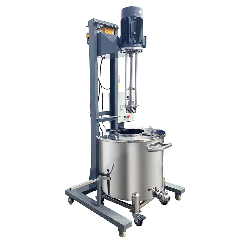
The Electric Lift High Shear Homogenizer combines a 4 kW top-entry rotor-stator head with a stainless steel vessel offering 200 L working capacity. Variable speed up to 3000 rpm supports emulsification and homogenization of flowable ointments, emulsions, and compatible chemical liquids. Electric screw lifting provides an 800 mm stroke for head positioning and vessel access, while PLC and touchscreen controls support semi-automatic batch operation.
| Tank Structure | Single Layer (Storage / Mixing) | Max Lifting Height (mm) | 800 |
| Contact Material | SUS316L Stainless Steel | Discharge Valves | Butterfly Valve |
| Outer Material | Painted Carbon Steel (Frame) | Connection Type | Tri-Clamp |
| Surface Finish | Inside & Outside Mirror Polished Finish | Motor Brand | SEW / ABB / Siemens |
| Surface Roughness | Ra ≤ 0.4 μm (Sanitary Grade) | mix_electrical_components | Standard Chinese Brand: DELIXI / CHINT / People Electric / TENGEN |
| Full Capacity (L) | 250 | Voltage | Configurable to local grid (110V–480V, 50/60Hz, Single or 3-Phase) |
| Working Capacity (L) | 200 | Total Power (kW) | 4.5 |
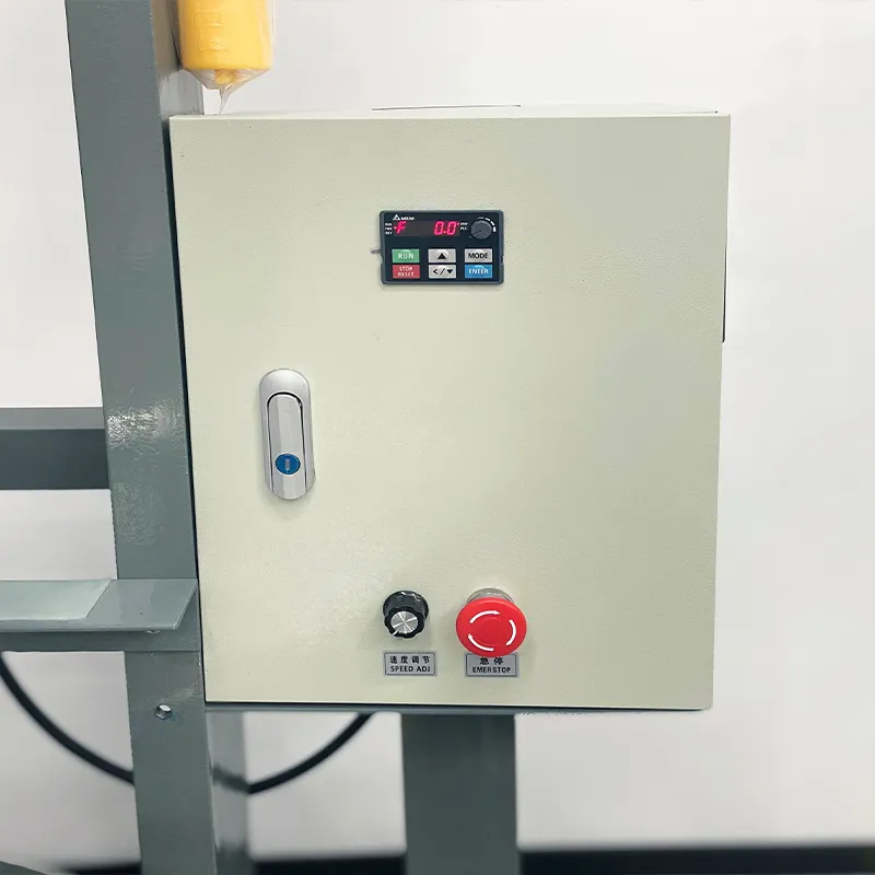
| Frequency Converter | Variable Speed with VFD (Delta, Siemens, ABB, Schneider, Optional) | Drive Type | Electric |
| Homogenizer Position | Top-Entry Homogenizer | Installation Type | Mobile (Caster-Mounted) |
| Homogenizer Speed (rpm) | 0–3000 rpm (Variable Frequency Control) | Automation Level | Semi-Automatic |
| Homogenizer Power (kW) | 4 | Control System | PLC + HMI Touch Screen Control |
| Rotor Stator Type | Single-Stage Rotor Stator | Machine Dimensions(L*W*H)mm | 1000*1000*2100 |
| Lifting Method | Electric Screw Lifting | Machine Weight (kg) | 150 |
Product Gallery
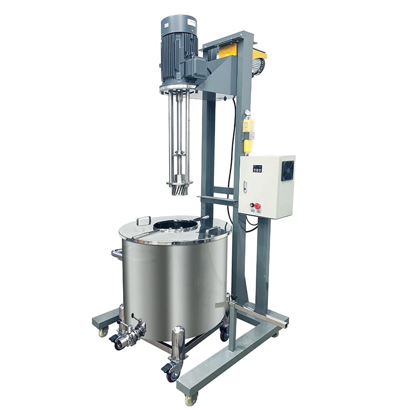
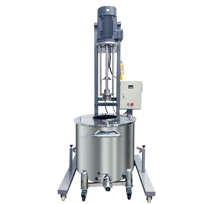
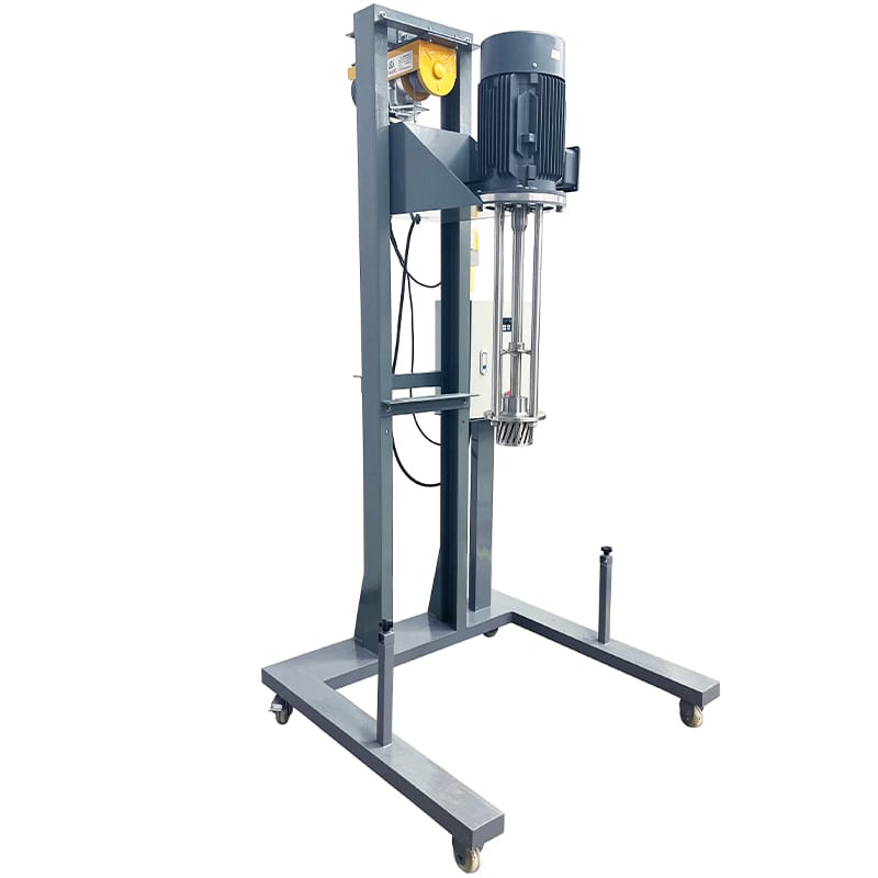



Product Video
Product Overview
StriversMachinery’s movable electric-lift homogenizer provides an integrated vessel-and-mixing arrangement for flowable products requiring rotor-stator processing. The supplied single-layer stainless steel vessel has a total capacity of 250 L and a working capacity of 200 L.
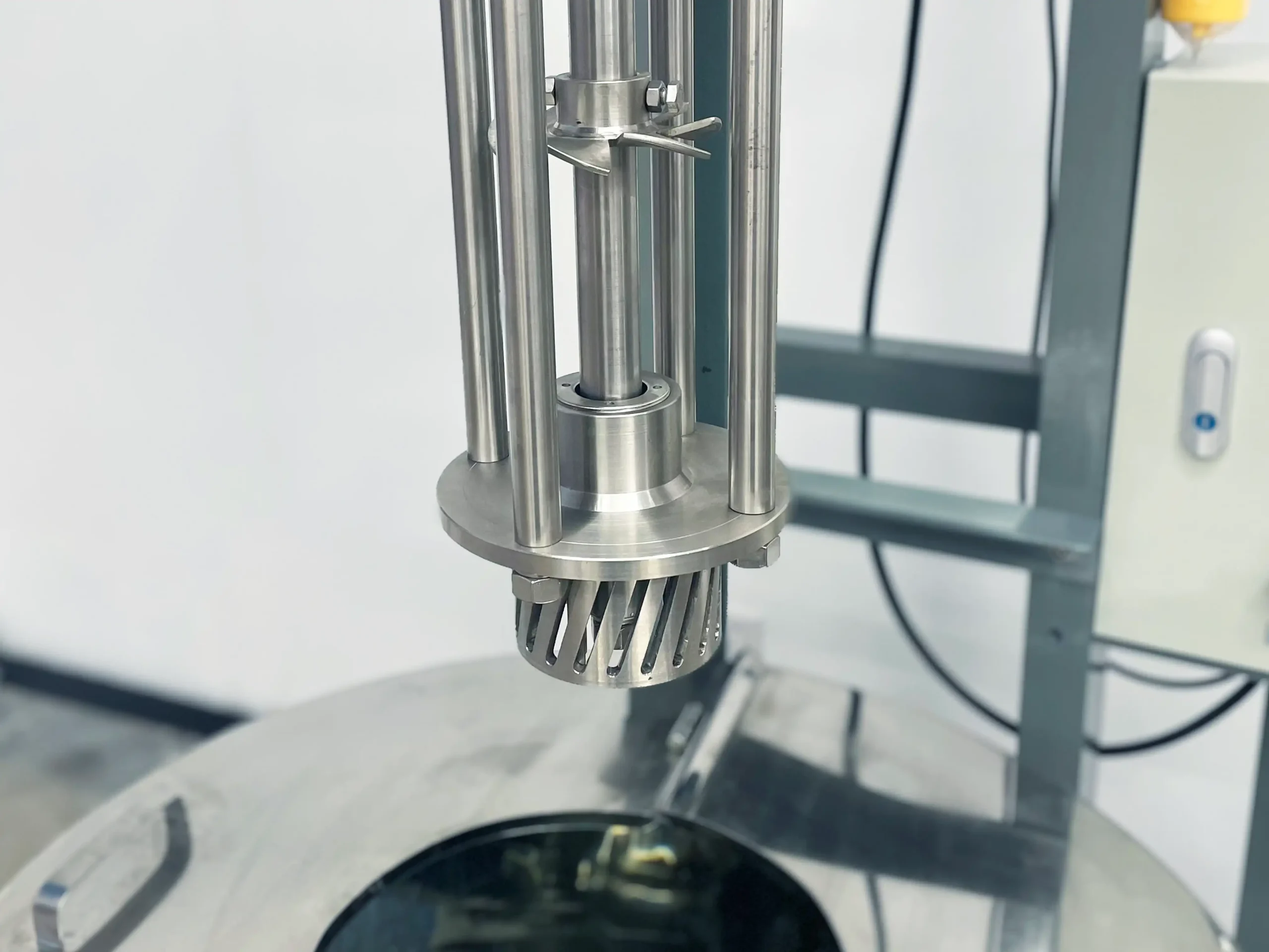
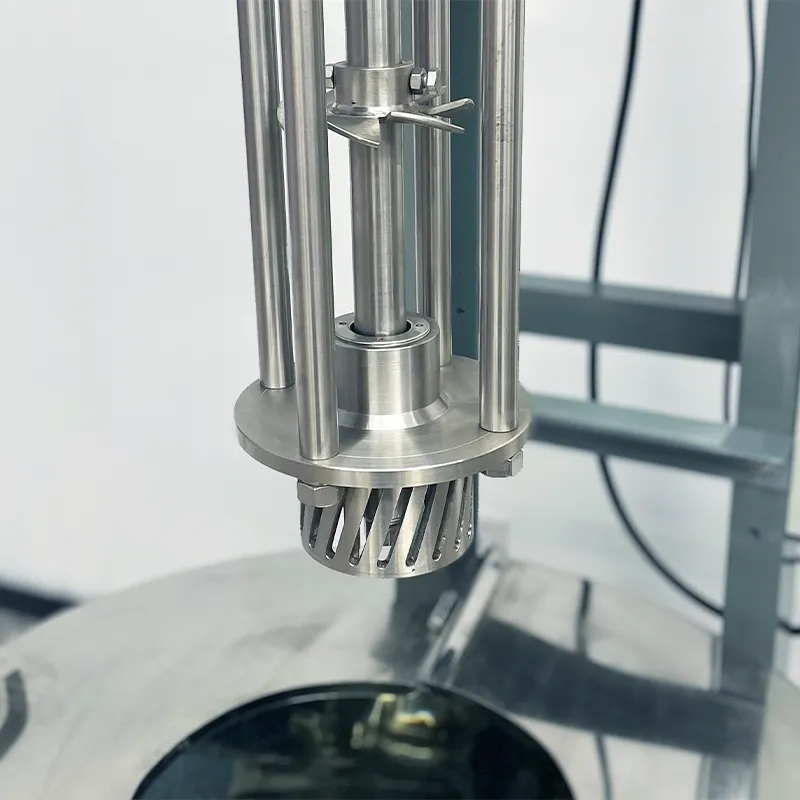
A 4 kW top-entry homogenizer uses a single-stage rotor-stator assembly to create localized high shear. Variable-frequency control adjusts speed up to 3000 rpm, allowing the processing conditions to be selected for the formulation. Typical applications include flowable ointments, emulsions, and compatible chemical liquids that can circulate through the working head.
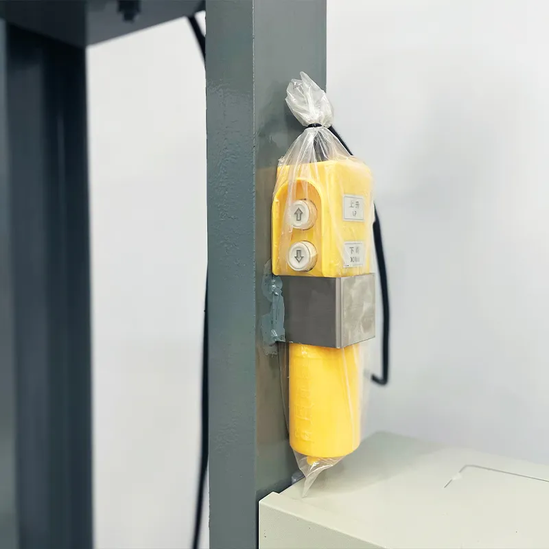
The electric screw lifting mechanism provides an 800 mm stroke for positioning the homogenizer and accessing the vessel. Product-contact components are SUS316L stainless steel. A butterfly discharge valve and Tri-Clamp connections support product discharge and component access.
PLC and touchscreen controls provide the operating interface. The supporting frame can be specified in painted carbon steel or SUS304 stainless steel, according to the installation requirements. The listed machine dimensions are 1000 × 1000 × 2100 mm, with a weight of approximately 150 kg.
The configuration focuses on mechanical emulsification and homogenization. It has no integrated heating, cooling, vacuum, or independent wall-scraping agitator. For related product applications, see ointment manufacturing equipment.
Machine Configuration
The machine combines a supplied 250 L single-layer vessel, rated for 200 L working capacity, with an electrically lifted top-entry homogenizer. Its single-stage rotor-stator head is driven by a 4 kW motor with variable-frequency speed control up to 3000 rpm.
- Electric screw lifting with an 800 mm stroke.
- PLC and HMI touchscreen operating controls.
- SUS316L product-contact components.
- Mirror-polished vessel surfaces with specified surface roughness of Ra ≤ 0.4 μm.
- Butterfly discharge valve and Tri-Clamp connections.
- Painted carbon steel or SUS304 stainless steel frame selection.
- Caster-mounted mobile installation.
The listed total power is 4.5 kW. Motor selection is specified from SEW, ABB, or Siemens, while available VFD selections include Delta, Siemens, ABB, and Schneider. Electrical component selection follows the ordered configuration. Supply voltage, frequency, and phase are agreed for the installation.
Key Features
- A supplied stainless steel vessel provides 250 L total and 200 L working capacity.
- The 4 kW top-entry homogenizer uses a single-stage rotor-stator working head.
- Variable-frequency control adjusts homogenizer speed up to a maximum of 3000 rpm.
- Electric screw lifting provides an 800 mm stroke for working-head positioning.
- PLC and touchscreen controls provide a centralized interface for machine operation.
- SUS316L product-contact components serve compatible emulsions, flowable ointments, and chemical liquids.
- Butterfly valve discharge and Tri-Clamp connections support routine product handling.
- Painted carbon steel and SUS304 stainless steel frame options suit different installation requirements.
Applications
- Cosmetic Cream & Lotion, and Skin Care
- Detergents, Liquid Washing & Household Cleaning
Recommended Machines

100L Hydraulic Lift Vacuum Emulsifying Mixer with Button Control for Cosmetic Cream and Lotion Production
View Details
7.5kW Hydraulic Lifting High Speed Disperser Machine for Paint, Coating, Ink & Chemical Liquid Mixing
View Details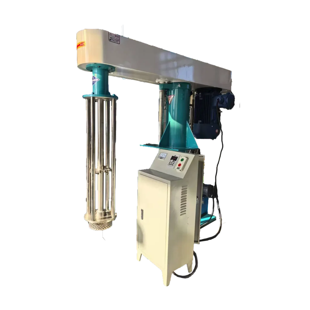

Working Principle
The electric-lift homogenizer processes a batch by circulating material through a top-entry rotor-stator head inside the supplied vessel. The electric screw mechanism positions the working head, while the separate homogenizer motor provides the rotating action.
Before processing, the operator charges the vessel according to the established batch procedure. The working head is lowered to an appropriate immersed position. Its operating depth must suit the batch level and vessel geometry so material can enter and leave the head without obstruction.
During operation, the rotor turns inside the stationary stator. Material entering the working head passes through the active rotor-stator region, where rapid velocity differences produce localized shear. The processed material returns to the surrounding batch, and continued circulation brings further material through the head.
This action supports droplet breakup during emulsification and reduction of compatible agglomerates during homogenization. The result depends on formulation, circulation, head geometry, speed, and processing time. The VFD allows speed adjustment up to 3000 rpm; the maximum setting is not automatically the correct setting for every product.
After the batch reaches its required condition, the operator stops the homogenizer and waits for complete standstill. Product is discharged through the butterfly valve according to the handling procedure. The electric lifting mechanism raises the assembly for vessel access and cleaning. PLC and touchscreen controls coordinate machine operation without adding heating, vacuum, or wall-scraping functions.
Optional Upgrades & Configurations
| Warranty | 24 Months | Payment Terms | 40% T/T Deposit, 60% Balance Before Shipment (Alibaba Trade Assurance Available) |
| Lead Time | 15–20 Working Days | Packaging | Standard Export Fumigation-Free Wooden Case |
After-Sales & Technical Support
🔧 Common Problems
Possible operating symptoms include uneven product appearance, remaining agglomerates, inconsistent viscosity between samples, or visible separation after processing. Material may circulate strongly near the working head while moving weakly near the vessel wall. Foaming, surface vortexing, splashing, or an unexpected temperature rise may appear during operation. Other symptoms include unusual shaft vibration, abnormal noise, unstable speed, or a drive warning. The electric lifting assembly may move unevenly, stop before the intended position, or fail to maintain the required clearance. During discharge, product may flow slowly, remain in the vessel, or leak at a valve connection. Residue may remain around the working head, outlet, or connection areas after cleaning.
🛠 Troubleshooting
Problem: Product uniformity differs between samples. Possible Cause: Inadequate batch circulation, an unsuitable head position, or a formulation that is too resistant to flow. Recommended Solution: Review observed circulation and the actual batch condition before changing speed or extending processing.Problem: Excessive foam or surface vortexing develops. Possible Cause: Unsuitable head immersion, operating speed, or batch level. Recommended Solution: Reassess the head position and operating settings against the approved batch procedure.Problem: Product temperature rises beyond the process target. Possible Cause: Prolonged shear exposure or an operating condition unsuitable for the formulation. Recommended Solution: Stop or adjust processing under the product procedure and review whether separate temperature control is required.Problem: Unusual vibration or noise occurs. Possible Cause: Product buildup, loose components, or damage affecting the rotating assembly. Recommended Solution: Stop and isolate the machine before inspecting accessible components and the working head.Problem: The electric lift moves unevenly or stops unexpectedly. Possible Cause: An obstruction, mechanical loading problem, or electrical fault. Recommended Solution: Secure the assembly under the maintenance procedure and arrange qualified inspection before further movement.Problem: Product discharge is slow or a connection leaks. Possible Cause: Restricted flow, an unsuitable transfer arrangement, or an incorrectly assembled connection. Recommended Solution: Inspect the outlet and connection after safe isolation before assessing valve or gasket replacement.
🧼 Cleaning Method
1. Stop the homogenizer according to the operating procedure. 2. Wait for the rotor and shaft to reach a complete standstill. 3. Discharge residual product through the established handling procedure. 4. Raise the assembly to the prescribed cleaning-access position. 5. Secure the raised assembly against unintended movement. 6. Isolate the electrical supply under the maintenance procedure. 7. Remove accessible product-contact components according to the machine instructions. 8. Clean the vessel interior with a method compatible with the formulation and materials. 9. Clean accessible rotor-stator surfaces and openings according to the working-head instructions. 10. Clean the butterfly valve and accessible discharge connections. 11. Inspect connection gaskets for residue or visible deterioration. 12. Rinse reusable product-contact components according to the approved cleaning method. 13. Wipe external surfaces without flooding electrical or lifting components. 14. Inspect cleaned surfaces for retained product or cleaning residues. 15. Dry components using the established production procedure. 16. Reassemble removed parts according to the machine instructions. 17. Record cleaning completion according to the facility’s requirements.
📋 Maintenance
1. Inspect accessible rotor and stator surfaces for wear, damage, or product buildup. 2. Examine the homogenizer shaft for visible deterioration or uneven running. 3. Check working-head attachments against the machine’s fastening instructions. 4. Inspect the electric lifting assembly for obstruction, wear, or abnormal movement. 5. Examine accessible frame fasteners for loosening. 6. Check the vessel supports and installed restraint arrangement for damage. 7. Inspect casters for wear affecting stable positioning. 8. Examine the butterfly valve for leakage or irregular operation. 9. Inspect Tri-Clamp connections and gaskets for damage or deterioration. 10. Keep motor and VFD ventilation openings clear of accumulated material. 11. Check touchscreen and control components for visible damage. 12. Review electrical connections through qualified maintenance personnel. 13. Apply lubrication only at the locations specified in the equipment instructions. 14. Replace worn components with parts matched to the installed configuration. 15. Verify lift operation after maintenance affecting the lifting assembly. 16. Check homogenizer operation after maintenance affecting rotating components. 17. Record inspections, adjustments, and component replacements in the maintenance log.
⚙️ Installation
1. Position the machine on a firm, level floor. 2. Establish clearance for vessel access and the complete lifting movement. 3. Secure the mobile assembly using its prescribed installation arrangement. 4. Inspect the supplied vessel and working head for transport damage. 5. Assemble the discharge valve and connections according to the machine instructions. 6. Connect protective earthing through qualified electrical personnel. 7. Connect the electrical supply specified for the ordered configuration. 8. Inspect working-head attachments before commissioning. 9. Check electric lifting movement under the commissioning procedure. 10. Verify motor rotation according to the equipment instructions. 11. Position the working head for the approved trial batch. 12. Conduct a controlled processing trial with representative material. 13. Assess circulation throughout the vessel. 14. Evaluate the processed product against the agreed acceptance criteria. 15. Check discharge operation using the intended handling arrangement. 16. Document the accepted operating setup before routine production.
🔩 Spare Parts
Why Choose This Machine
- Defined vessel and batch relationship: The supplied 250 L vessel and 200 L working capacity provide a clear starting point for production planning and equipment layout.
- Focused rotor-stator processing: The single-stage working head applies localized shear for compatible emulsification and homogenization duties rather than relying on simple bulk stirring alone.
- Adjustable operating intensity: Variable-frequency control allows speed selection for the formulation and processing stage within the available operating range.
- Accessible vessel arrangement: Electric lifting helps clear the working head from the vessel for inspection and cleaning after rotation has stopped.
- Choice of supporting structure: Painted carbon steel and SUS304 frame options allow the supporting structure to be selected separately from the SUS316L product-contact components.
- Practical discharge connection: The butterfly valve and Tri-Clamp arrangement provide a defined product outlet for connection to a suitable downstream handling system.
- Centralized operation: PLC and touchscreen controls bring machine operation to one interface, supporting routine setup and batch supervision.
Frequently Asked Questions
Installation Requirements
Check the complete lifting movement against overhead obstructions. The 800 mm stroke describes travel, while the listed overall height does not establish the maximum raised envelope. Keep access clear around the lifting assembly and vessel.
The electrical supply must match the ordered motor, VFD, and control system. The listed total machine power is 4.5 kW. Arrange protective earthing and electrical connection through qualified personnel using the machine’s wiring requirements.
Establish an appropriate method of restraining the mobile machine and vessel during operation. Position the discharge connection so product handling does not obstruct controls or access routes.
Provide a cleaning arrangement compatible with the product and installed materials. Site ventilation, chemical compatibility, and any requirements associated with flammable products must be assessed for the application. The standard configuration does not require a heating, cooling, vacuum, or pneumatic lifting utility connection.
Related Articles


Technical Buyer's Handbook & Deep Insight
Ready to Get a Quote?
Contact our team directly for pricing, customization options, and delivery timelines.
💬 WhatsApp Us NowGet Your Download Link
Please fill in your details and we'll send the download link to your email.