
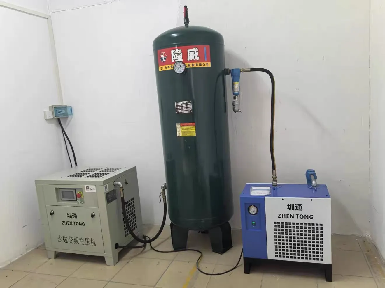
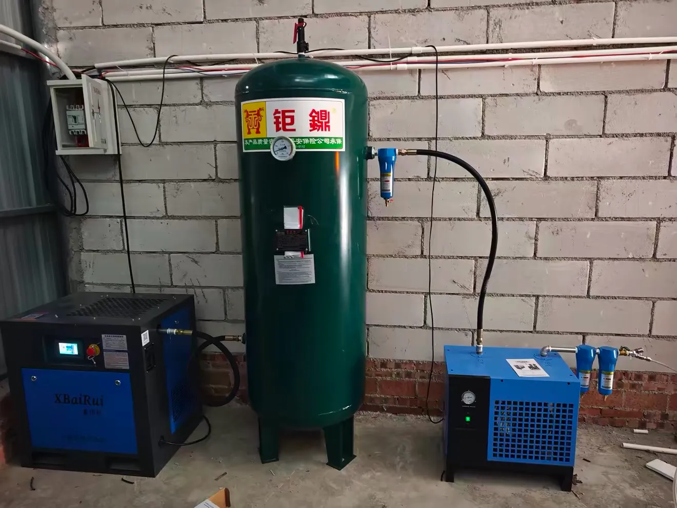
7.5kW permanent-magnet variable-frequency screw air compressor + 1m³ air receiver tank + refrigerated air dryer
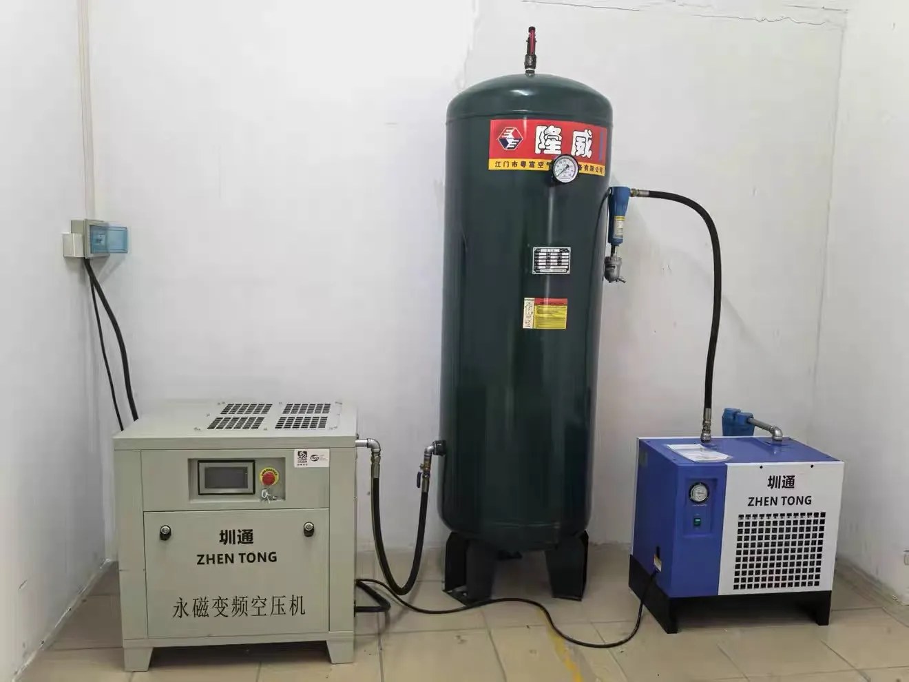
The 7.5kW screw air compressor system combines a permanent-magnet variable-frequency compressor, a 1m³ vertical receiver and a refrigerated dryer for general industrial pneumatic service. Model STKYJ-7.5 provides air generation, storage and moisture treatment in three separate units. It can support the pneumatic functions of filling machines and other workshop equipment where the required flow, pressure and air quality match the specified configuration.
| Model | STKYJ-7.5 | Drive Type | Electric |
| Equipment Type | Air Compressor | Installation Type | Floor-Standing |
| Output / Capacity | 7.5 kW | Automation Level | Fully Automatic |
| Fuel / Energy Type | Electric | Control System | PLC + HMI Touch Screen Control |
| Compressed Air Quality | General Industrial Grade | Control & Interaction Systems | Semi-Automated (Efficiency-Focused) |
| Noise Level (dB(A)) | 65 | Machine Dimensions(L*W*H)mm | 740*570*790 |
| Voltage | Configurable to local grid (110V–480V, 50/60Hz, Single or 3-Phase) | Machine Weight (kg) | 265 |
| Total Power (kW) | 7.9 | ||
Product Gallery
Product Overview
STKYJ-7.5 is a floor-standing compressed air package for factories that need a coordinated supply for pneumatic actuators, valves and handling equipment. It brings together three functions that would otherwise need separate selection: compression, short-duration storage and refrigerated moisture removal.
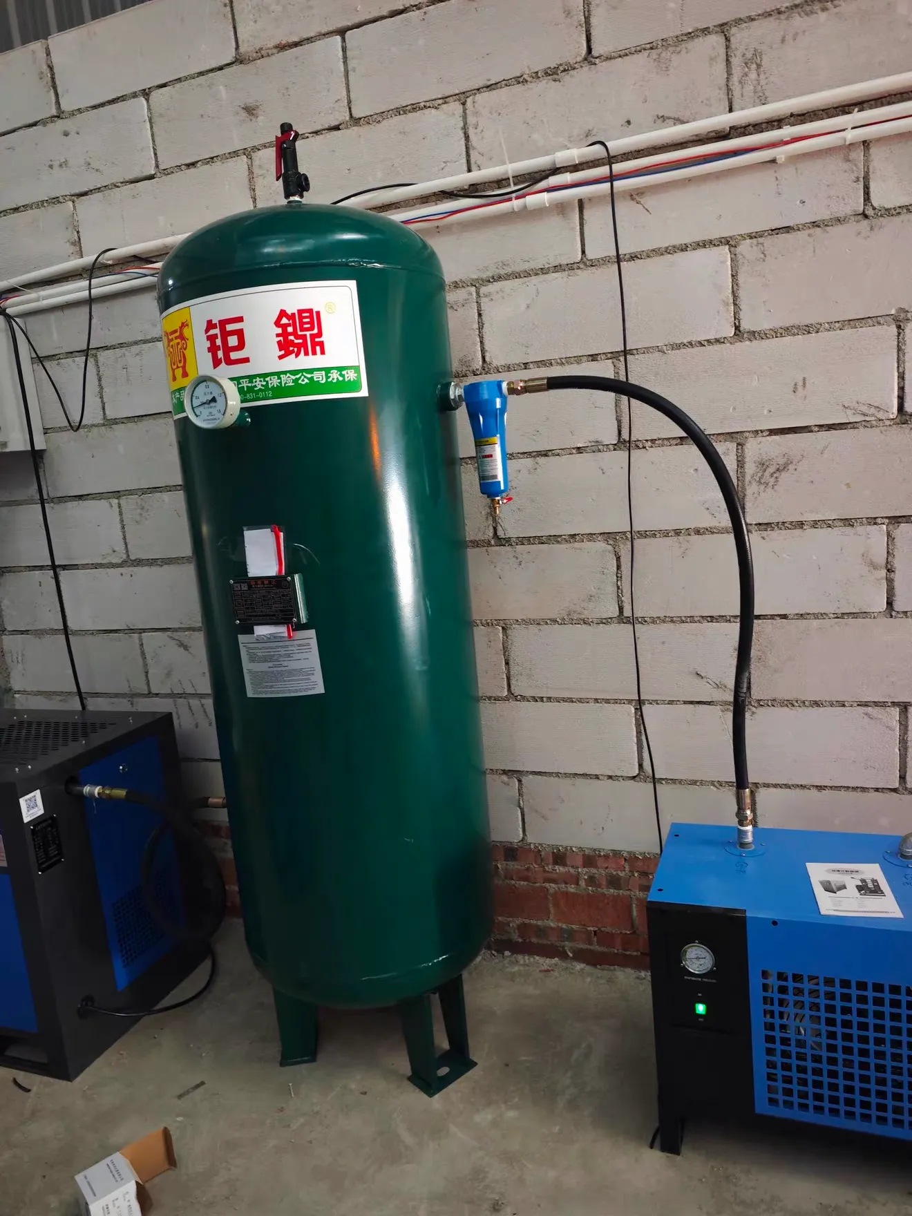
The compressor generates the air supply, while the vertical receiver provides a buffer between production and consumption. The dryer treats moisture before air is delivered through the approved distribution arrangement. The units are connected with hoses, allowing their positions to be coordinated with ventilation, drainage and maintenance access rather than requiring a single combined footprint.
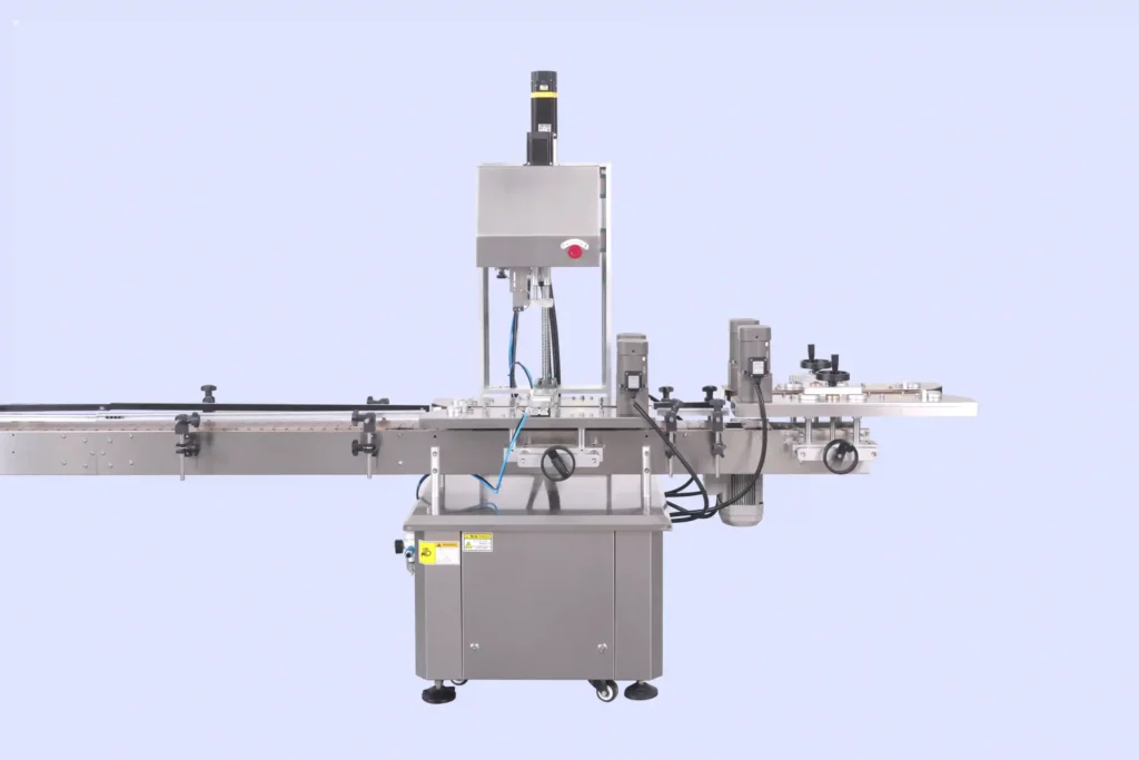
For capping machines and similar intermittent users, the important selection question is whether sufficient pressure remains available during overlapping demands. An automatic line may consume air in short bursts even when its average demand appears modest. The receiver helps accommodate these changes, but cannot compensate indefinitely for insufficient compressor output.
This package is part of the factory’s utility systems. It supplies general industrial air rather than establishing a product-contact air specification. Buyers should identify each connected user and confirm its required operating pressure, consumption and treatment requirements before finalizing the supply scope.
Machine Configuration
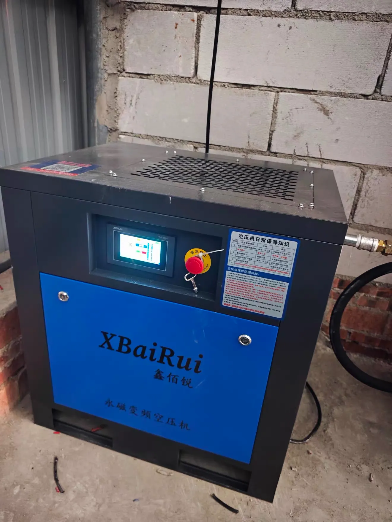
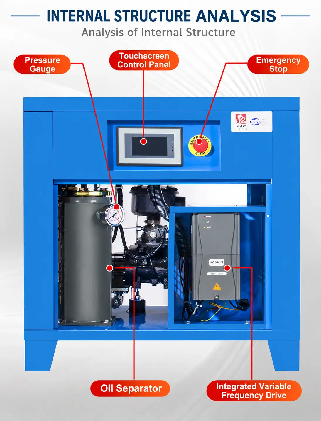
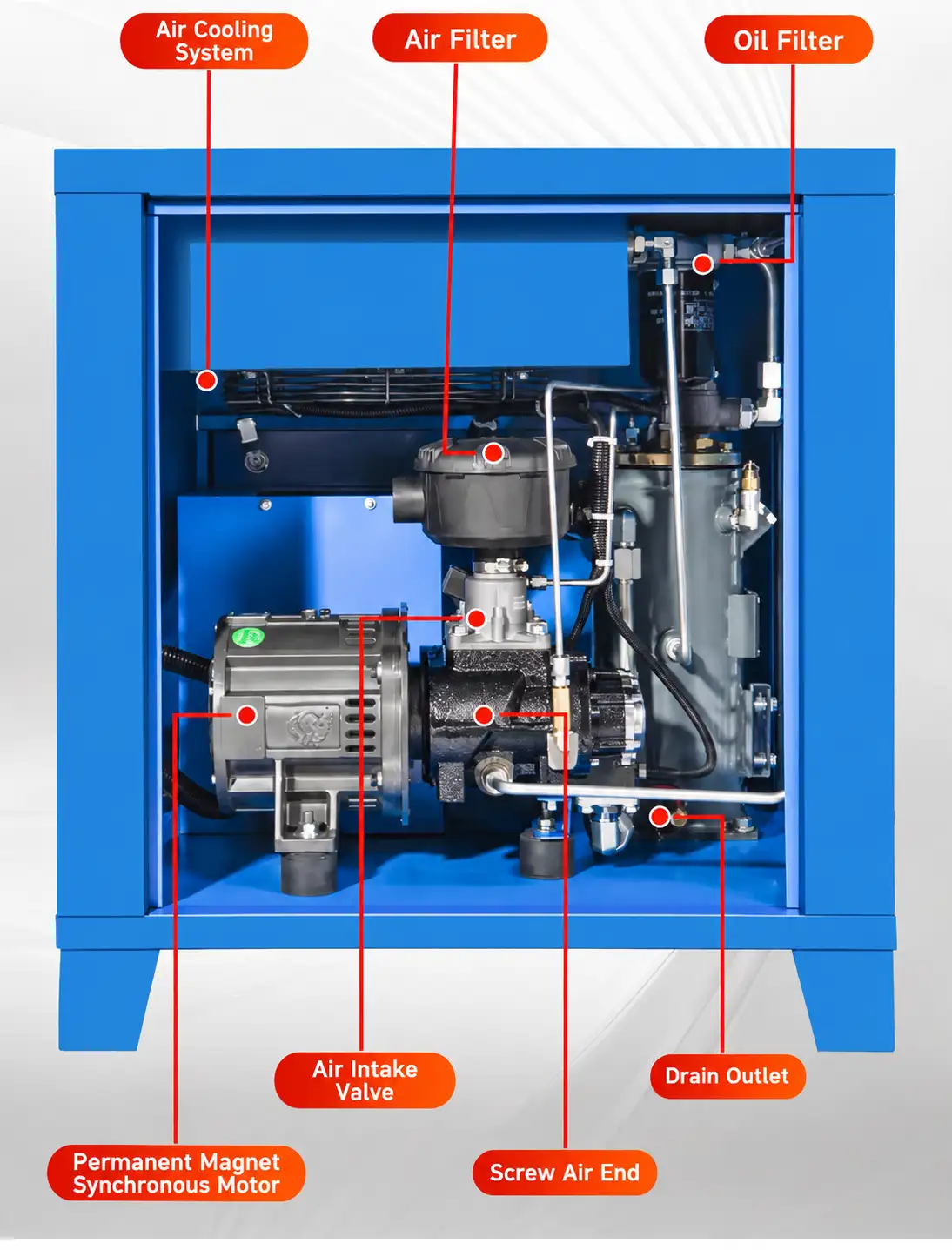
The compressor uses a permanent-magnet synchronous motor, variable-frequency drive and screw air end. Its oil circuit includes an oil filter and oil–air separator, so the package must not be described as oil-free. Air cooling and cabinet ventilation manage operating heat.
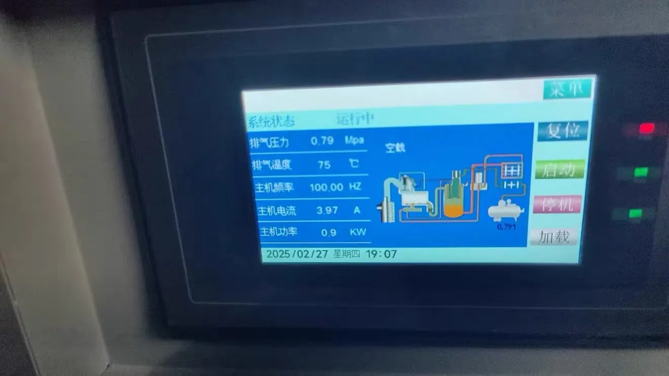
A PLC and touchscreen provide operating commands and displayed status, including the listed pressure, temperature and motor information. The emergency-stop control is separate from the isolation required for servicing.
The vertical receiver has a pressure gauge, safety valve and bottom drain. The refrigerated dryer has its own power indication, pressure gauge and air-cooled condenser. The compressor and dryer require their specified electrical supplies.
Confirm the final piping order, hose ratings, drain connections and any line filters on the approved layout. Mention of a precision filter in the supplied description does not define its quantity, grade or installation position.
Key Features
- Variable-speed compression adjusts motor operation within the installed system’s permitted demand range.
- A separate receiver buffers short changes in pneumatic demand between connected users.
- Refrigerated drying removes condensed moisture without requiring a desiccant regeneration cycle.
- Touchscreen status information supports routine observation from the normal operator position.
- Separate floor-standing units allow layout planning around existing workshop service routes.
- Vertical air storage limits the receiver’s floor occupation while requiring overhead clearance.
- Dedicated condensate drain points make moisture removal an identifiable operator responsibility.
- Accessible cabinet and condenser ventilation support planned inspection and external cleaning.
Applications
- Cosmetic Cream & Lotion, and Skin Care
- Detergents, Liquid Washing & Household Cleaning
- Hair Care, Personal Care & Body Wash
Recommended Machines

300L Perfume Making Machine with Chilling Freezing Filtration & Pneumatic Agitator for Eau de Toilette, Cologne & Essential Oil Processing
View Details
48kW Industrial Electric Steam Generator Boiler for Reaction Vessel, Emulsifier & Sterilization
View Details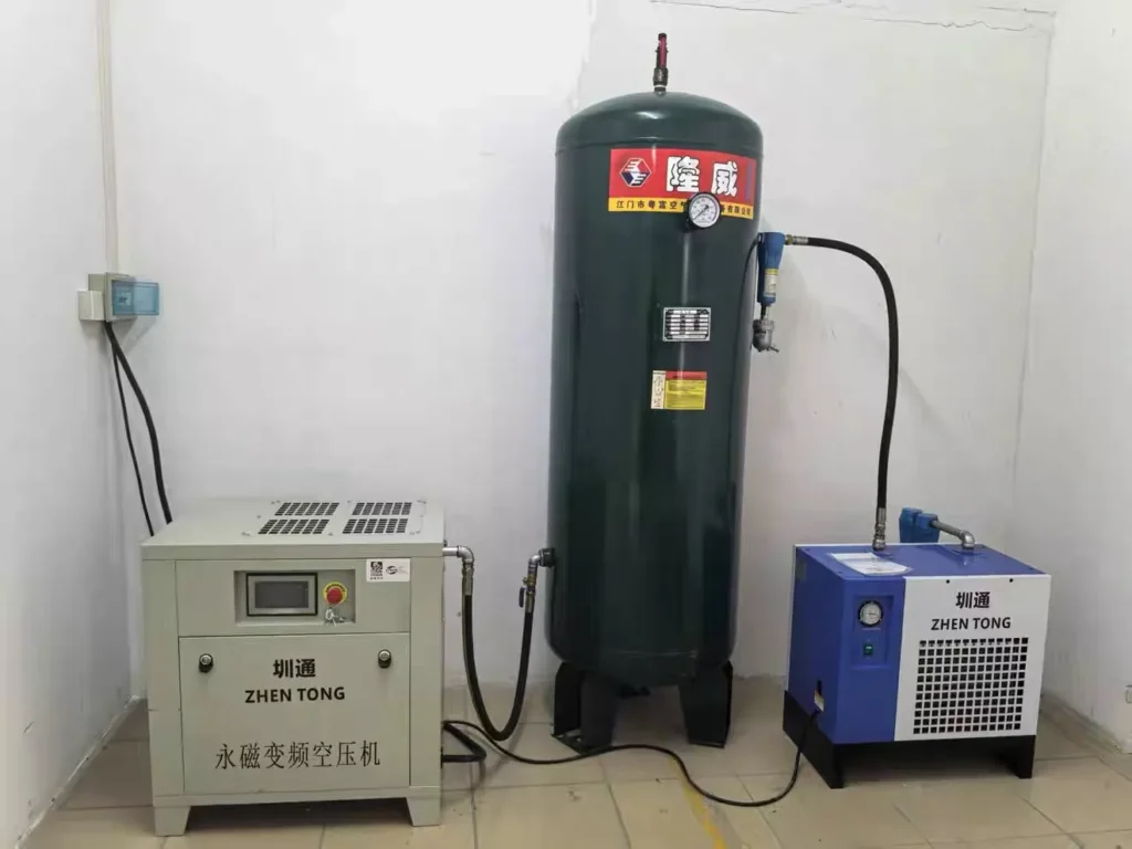
Working Principle
Ambient air enters the compressor through the intake filter and inlet-control assembly. The permanent-magnet motor drives the screw air end, where the air is compressed. The lubricating-oil system supports the compression assembly, and the installed separator reduces oil carry-over before the air leaves the compressor. Separation is not the same as producing oil-free air.
The variable-frequency control adjusts motor operation in response to demand and pressure within the machine’s programmed operating limits. At very low demand, the control may need its specified unload or stop sequence; variable speed does not imply unlimited turndown. The operator uses the touchscreen to observe status and respond to alarms rather than bypassing them.
Air storage and treatment follow the approved system connection drawing. The receiver stores compressed air and releases it as downstream demand changes. A drop in receiver pressure indicates that air is being consumed faster than it is being replenished over that period. Storage smooths a transient imbalance but does not create additional continuous compressor capacity.
Inside the refrigerated dryer, cooling causes part of the water vapor to condense. The condensate is separated and discharged through the specified drain arrangement. Remaining moisture depends on the dryer’s actual performance and conditions. Any downstream particle, aerosol or vapor treatment must be selected separately for the required air specification. The resulting air is distributed to compatible pneumatic users through rated hoses, pipework and point-of-use controls.
Suitable Products
| Warranty | 24 Months | Payment Terms | 40% T/T Deposit, 60% Balance Before Shipment (Alibaba Trade Assurance Available) |
| Lead Time | 15–20 Working Days | Packaging | Standard Export Fumigation-Free Wooden Case |
After-Sales & Technical Support
🔧 Common Problems
Operators may observe pressure falling during simultaneous machine cycles, slow recovery after a production stop, repeated loading and unloading, or an unstable pressure indication. Other symptoms include visible moisture at a downstream drain, water appearing at a pneumatic device, abnormal oil carry-over, or a change in compressor sound or vibration. The touchscreen may display an operating-temperature warning, a drive alarm or a service indication. The dryer may show an unexpected status, fail to start, or leave an unusual amount of condensate downstream. Leaks may be audible around hoses or fittings, and connected actuators may move slowly or inconsistently. Record the displayed condition and affected operating state before arranging investigation.
🛠 Troubleshooting
Problem: Pressure falls during overlapping production cycles. Possible Cause: Combined demand, leakage or a restricted distribution path may exceed available delivery. Recommended Solution: Record the operating users and pressure at accessible designated points; arrange a capacity, leak and pressure-drop review before changing approved settings.Problem: Water appears downstream of the dryer. Possible Cause: An inactive drain, incorrect dryer operation, unsuitable loading or condensation in colder pipework may be involved. Recommended Solution: Check the permitted status indications and drain condition; have qualified personnel compare actual conditions with the dryer rating and required dew point.Problem: The compressor displays a high-temperature alarm. Possible Cause: Restricted external airflow, recirculated hot air or a cooling or lubricant-system fault may be involved. Recommended Solution: Follow the alarm shutdown instructions; have authorized service personnel investigate after the required isolation and cooling, without bypassing protection.Problem: Oil carry-over increases. Possible Cause: Service condition, an unsuitable lubricant level or separation-system deterioration may be involved. Recommended Solution: Record operating conditions and arrange inspection against the exact service manual before replacing a separator or adjusting the oil system.Problem: The dryer does not start. Possible Cause: Supply, protection, an operating delay or an equipment fault may be involved. Recommended Solution: Check the operator-accessible indication; refer supply and internal checks to qualified personnel without repeatedly resetting protective devices.
🧼 Cleaning Method
1. Follow the documented shutdown procedure before preparing the package for external cleaning; an emergency condition requires its specified response instead. 2. Isolate each electrical supply under the site procedure to prevent an automatic restart during the cleaning task. 3. Isolate the relevant pneumatic section under the approved procedure before any work that could release stored air. 4. Verify the required zero-energy condition before touching components within the cleaning scope; a stopped motor does not prove depressurization. 5. Allow hot external surfaces to cool to the condition required by the equipment instructions. 6. Remove loose dirt from accessible cabinet surfaces using a method permitted by the manual. 7. Clean accessible ventilation and condenser surfaces with the specified non-damaging method, without opening the refrigerant circuit. 8. Wipe exterior panels with a compatible material while keeping moisture away from controls and electrical openings. 9. Collect any contaminated cleaning waste in the designated disposal system. 10. Inspect the cleaned areas before handing the package back for the separate authorized return-to-service procedure.
📋 Maintenance
1. Review the applicable operating-hours record and service instructions before planning maintenance for the installed compressor and dryer. 2. Record the permitted operator observations, including pressure, temperature, alarm status and changes from normal operation. 3. Prepare the equipment for servicing under its approved shutdown and isolation procedure. 4. Verify the relevant stored-pressure and electrical hazards have been controlled before the authorized task begins. 5. Inspect accessible hoses and connections for damage within the approved maintenance scope. 6. Check the external ventilation and condenser condition against the equipment instructions. 7. Have authorized personnel inspect the compressor lubricant condition using the machine-specific method. 8. Replace the intake filter, oil filter or separator only when required by the applicable manual and actual service condition. 9. Check condensate-drain function using the specified safe method and disposal arrangement. 10. Arrange receiver and safety-device examination at the intervals and scope required for the installation. 11. Record completed work before releasing the equipment through the approved recommissioning procedure.
⚙️ Installation
1. Approve the installation drawing against the agreed air-demand schedule and component documentation. 2. Confirm that the receiver documentation satisfies the applicable destination requirements before installation proceeds. 3. Prepare the designated level support area to the approved layout. 4. Position each unit using handling arrangements suitable for its confirmed mass and lifting provisions. 5. Provide the ventilation clearances specified by the installed equipment manuals. 6. Install the rated pneumatic connections in the approved flow order through qualified personnel. 7. Connect the designated condensate outlets to the approved collection arrangement. 8. Have a qualified electrical installer connect each supply to the final equipment schedule. 9. Have authorized personnel verify the safety arrangements before energization. 10. Commission the package using the manufacturer’s sequence and agreed pressure limits. 11. Observe representative simultaneous production demand from the normal operating positions. 12. Document acceptance results before handing the system over to trained operators.
🔩 Spare Parts
Why Choose This Machine
- Coordinated utility scope. Compression, buffering and moisture treatment can be reviewed together rather than treating the compressor alone as the complete air supply.
- Demand-responsive operation. Variable-frequency control can reduce unnecessary operation under suitable changing loads; actual electricity savings depend on the duty profile and settings.
- Intermittent-load support. Receiver storage provides a practical buffer for actuator cycles and short demand peaks, subject to the available pressure range.
- Layout flexibility. Separate units can be positioned around service access and heat rejection, provided hose lengths and pressure losses remain acceptable.
- Clear operator observations. Displayed operating information and local gauges provide reference points for routine checks and troubleshooting.
- Defined treatment boundary. A refrigerated dryer offers moisture control for suitable general industrial duties, while stricter air requirements can be evaluated explicitly.
- Production planning context. The package can be assessed alongside packaging equipment rather than selected only by motor power or receiver size.
Frequently Asked Questions
Installation Requirements
The detailed component schedule specifies 380V, three-phase, 50Hz for the compressor and 220V, single-phase, 50Hz for the dryer. A qualified electrical installer should confirm the final nameplates, protective devices, earthing and isolators. Do not use the unresolved package power figure as a cable-sizing instruction.
Provide ventilation that prevents hot discharge air from recirculating into the compressor or dryer condenser. Maintain the clearances required by the actual manuals, with room for service-panel access and replacement of maintenance elements. Review hot and humid site conditions against the dryer’s rating basis.
Use hoses, fittings and downstream pipework rated for the permitted operating conditions. Arrange condensate collection and lawful disposal; compressor condensate may contain oil. Ensure receiver inspection access, readable instruments and an unobstructed safety-valve discharge arrangement. Confirm destination-specific pressure-equipment documentation and inspection obligations before use. Site utilities should be coordinated with the factory’s broader service plan, including safe shutdown of dependent machines.
Related Articles


Technical Buyer's Handbook & Deep Insight
Ready to Get a Quote?
Contact our team directly for pricing, customization options, and delivery timelines.
💬 WhatsApp Us NowGet Your Download Link
Please fill in your details and we'll send the download link to your email.