
Portable Stainless Steel Rotary Lobe Pump with VFD for Cosmetic Lotions, Gels & Pharmaceutical Ointment Transfer
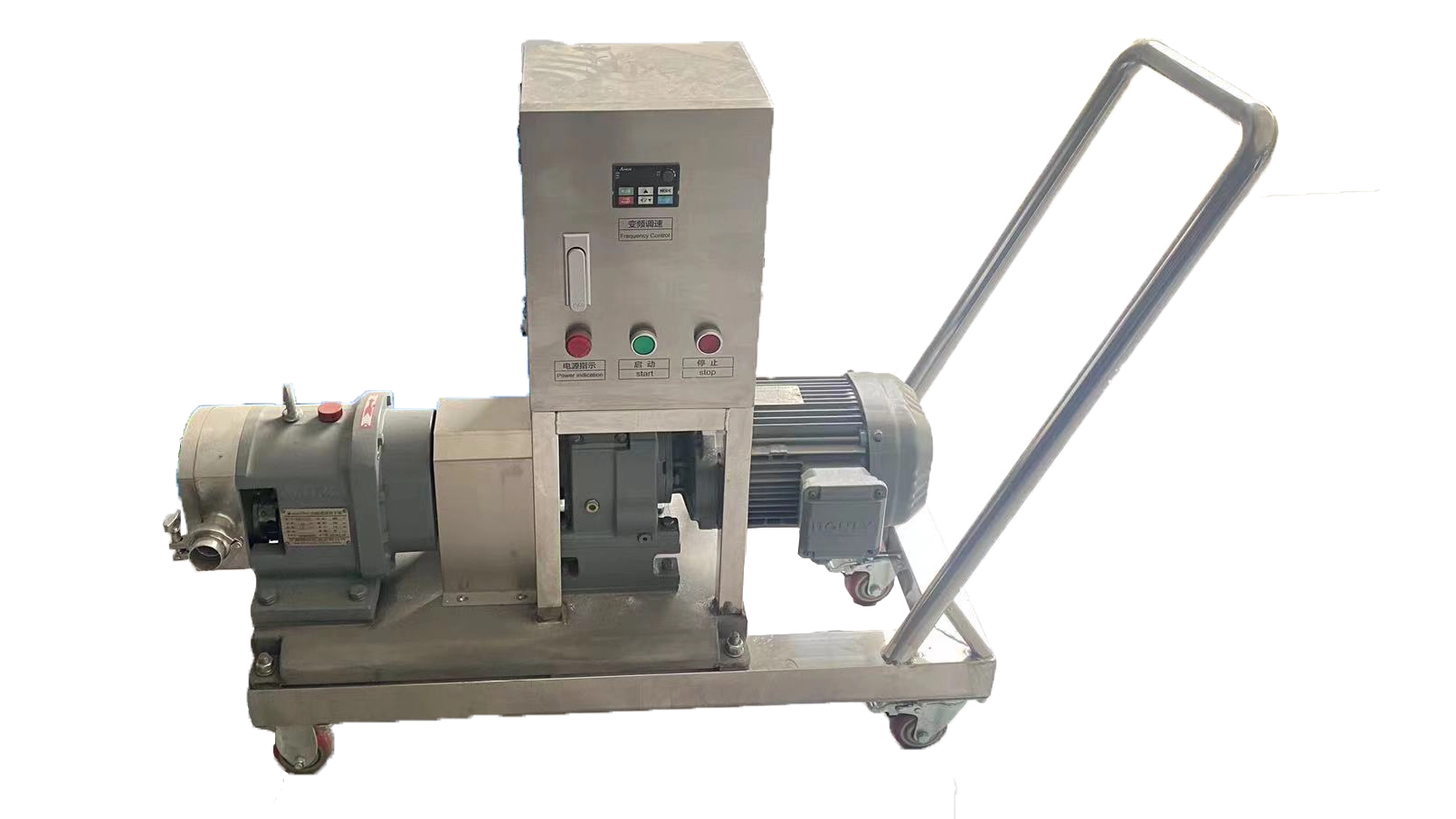
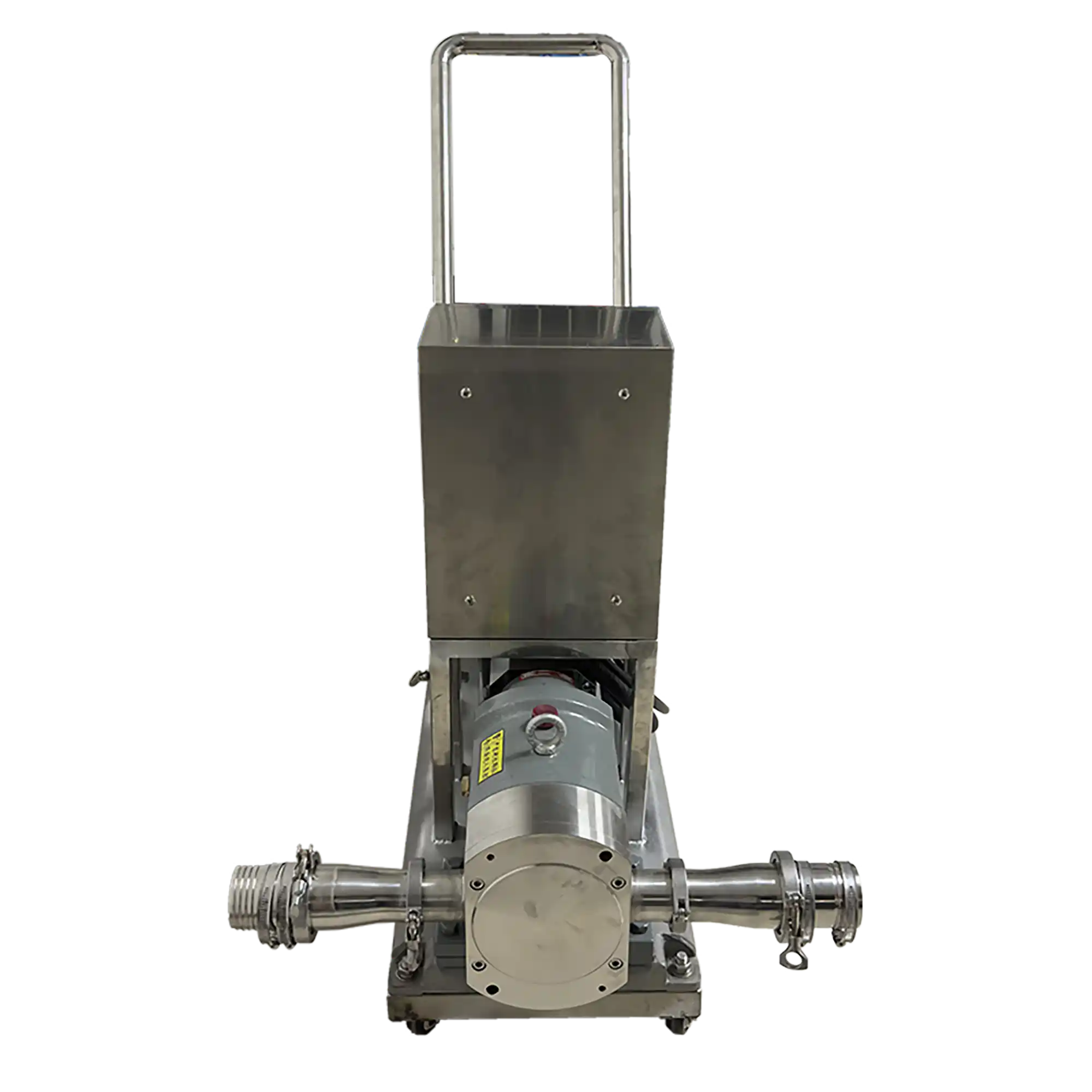
The Portable Rotary Lobe Pump transfers compatible cosmetic creams, lotions, gels, ointments, sauces, pastes, and emulsions between production stages. Variable-frequency speed control allows operators to adjust pumping to the transfer duty, while the mobile stainless steel trolley supports repositioning between suitable connection points. The electric unit uses button operation and provides product transfer rather than automatic batch weighing or quantitative filling.
| Pump Type | Sanitary Centrifugal Pump (CIP/Low-Viscosity) | Drive Method | Variable Frequency Drive (VFD / Inverter) |
| Flow Rate (m³/h) | 5 | Voltage | Configurable to local grid (110V–480V, 50/60Hz, Single or 3-Phase) |
| Operating Head Range (m) | 10–50 m (Equivalent to 0.1–0.5 MPa) | Total Power (kW) | 1.7 |
| Max Working Pressure (MPa) | 0.3–0.8 | Drive Type | Electric |
| Applicable Viscosity (cps) | 1-50000 | Installation Type | Mobile (Caster-Mounted) |
| Seal Type | Single Mechanical Seal | Automation Level | Semi-Automatic |
| Impeller / Rotor Material | SUS316L | Electrical Components | Schneider / ABB / Siemens / Omron / Fuji /Mitsubishi (Optional) / Top-tier Chinese Brand: DELIXI / CHINT / People Electric / TENGEN |
| Motor Power (kW) | 1.5 | Control System | Push Button Control |
| Pump Speed (rpm) | 334 | Machine Dimensions(L*W*H)mm | 1265*520*630 |
| Connection Standard | Tri-clamp Sanitary | Machine Weight (kg) | 120 |
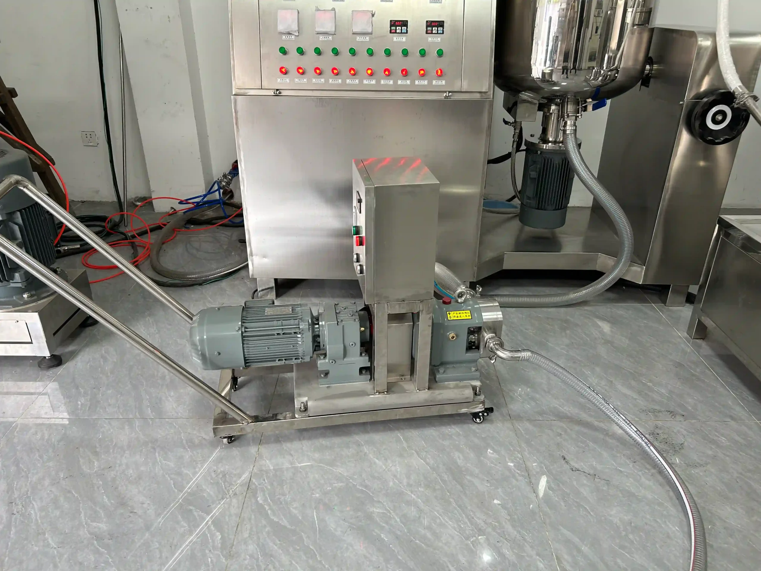
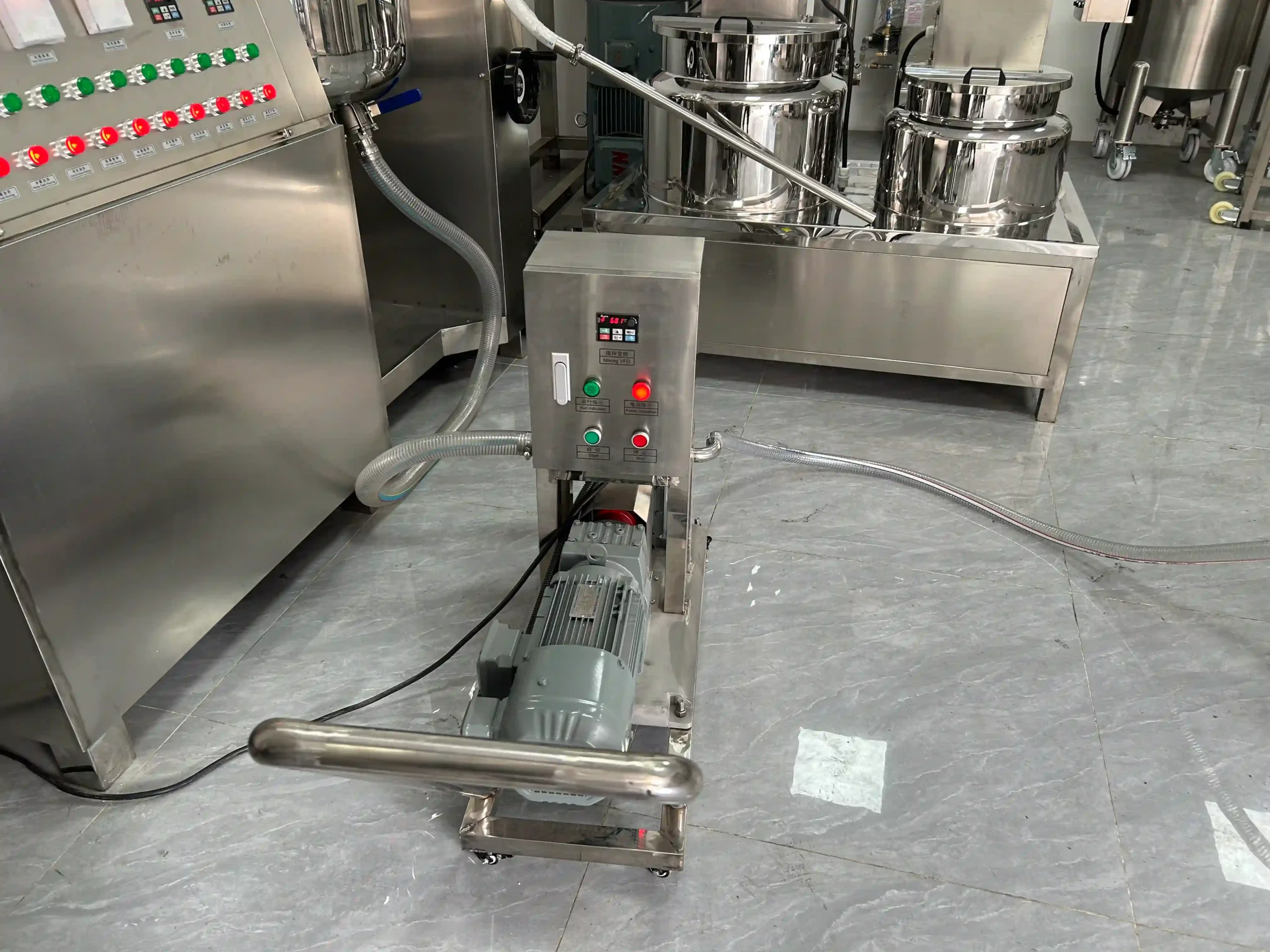
Product Gallery

Product Overview
StriversMachinery’s portable rotary lobe pump provides a movable transfer arrangement for compatible liquid and viscous formulations. It can be assessed for moving product from a processing vessel to holding, from storage to a filling supply point, or between other suitable stages of production.
The pump uses a rotary lobe mechanism rather than a centrifugal impeller. A variable-frequency drive adjusts operating speed so the transfer setup can be reviewed against product behavior, source conditions, and the receiving process.
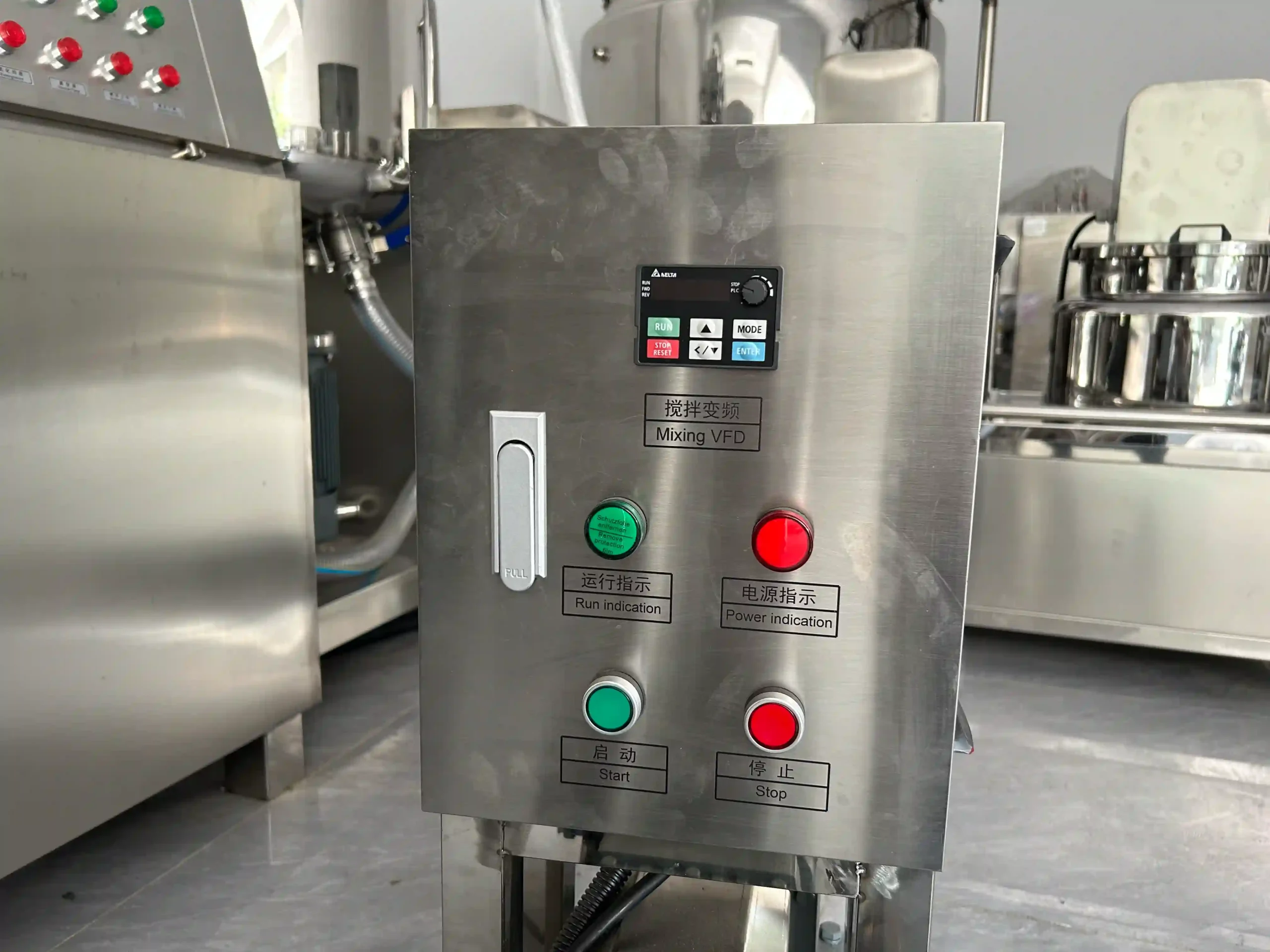
The stainless steel trolley brings the pump, drive, and local controls together. Tri-Clamp connections provide the interface for suitable product piping or hoses. Operators position the unit, establish the transfer route, and control operation through the button panel.
Metal product-contact components, including the pump chamber and rotors, are SUS316L stainless steel. A single mechanical seal is specified, with its contact materials and elastomers selected separately against the product and cleaning requirements.
Applications include compatible creams, lotions, gels, flowable ointments, sauces, and emulsions. Soft-particle products require assessment of particle characteristics, pump clearances, and the entire transfer route. Within the fluid transfer equipment range, this model focuses on mobile, variable-speed product movement.
Machine Configuration
The assembly combines a rotary lobe pump, electric motor, variable-frequency drive, local button controls, and a mobile stainless steel trolley. The handle and casters support movement between suitable operating positions, while product connections use Tri-Clamp fittings.
The pump chamber and rotors are SUS316L stainless steel. A single mechanical seal provides the confirmed shaft-sealing arrangement. Seal-face materials, elastomers, and connection gaskets require selection against the formulation and cleaning method.
VFD operation adjusts pump speed rather than directly measuring the quantity transferred. The described configuration does not include automatic weighing, batch-volume control, or a filling-nozzle system.
Electrical components follow the ordered specification. External hoses, source-vessel connections, receiving arrangements, and any required transfer-line protection must be defined in the project scope. The trolley’s stainless steel grade is not assigned.
Key Features
- Rotary lobe pumping moves compatible liquids, creams, pastes, and emulsions between production stages.
- Variable-frequency control adjusts operating speed to the selected transfer conditions.
- A mobile stainless steel trolley groups the pump, drive, and controls together.
- The trolley handle supports repositioning between suitable production connection points.
- Tri-Clamp connections provide an interface for matched product piping and hoses.
- SUS316L pump-chamber and rotor construction defines the metal product-contact specification.
- A single mechanical seal provides the confirmed shaft-sealing arrangement.
- Local button controls support operator-managed starting, stopping, and transfer supervision.
Applications
- Cosmetic Cream & Lotion, and Skin Care
- Hair Care, Personal Care & Body Wash
Recommended Machines


Working Principle
The portable rotary lobe pump moves product by carrying it through changing spaces between the rotating lobes and pump casing. The electric drive turns the pumping assembly, while the VFD allows operating-speed adjustment.
Before transfer, the operator positions and secures the trolley, connects the product source and destination, and prepares the route according to the pump instructions. The source must provide material to the inlet under conditions suitable for the actual formulation and installation.
As the rotors turn, product enters the pumping chamber and is carried around the casing toward the outlet. Continued rotation displaces the material into the connected transfer line. This is a positive-displacement pumping process, distinct from a centrifugal pump accelerating liquid with an impeller.
Changing speed changes the pumping action, but the actual delivered flow also depends on viscosity, inlet supply, line resistance, and operating conditions. The rated reference is 5 m³/h at 334 rpm; that reference is not a guarantee of identical flow for every product within the stated application range.
The single mechanical seal limits leakage at the shaft interface. Tri-Clamp fittings connect the pump to the selected product pathway.
The operator controls transfer through the local buttons and speed setting. The unit does not independently measure batch mass or stop at a programmed filling quantity. Transfer completion and subsequent cleaning follow the production procedure.
| Warranty | 24 Months | Payment Terms | 40% T/T Deposit, 60% Balance Before Shipment (Alibaba Trade Assurance Available) |
| Lead Time | 15–20 Working Days | Packaging | Standard Export Fumigation-Free Wooden Case |
After-Sales & Technical Support
🔧 Common Problems
Possible operating symptoms include reduced or interrupted flow, uneven product delivery, unusual noise, vibration, or visible air in the transferred material. Product may leak near the shaft-seal area, pump cover, or external connections. The pump or drive may show an unexpected temperature rise, and the VFD may display a warning or stop. Material may remain in the source vessel despite continued operation, or the receiving process may become unstable during transfer. Soft-particle products may show visible changes after pumping. Other observations include hose movement, trolley movement, retained product after drainage, or difficulty achieving the expected result after changing the transfer route.
🛠 Troubleshooting
Problem: Flow is lower than expected. Possible Cause: Restricted inlet supply, changing product viscosity, or resistance in the transfer route. Recommended Solution: Review the source, product condition, and connected line before increasing speed.Problem: Delivery becomes irregular or air appears in the product. Possible Cause: An interrupted source supply, leakage at an inlet connection, or unsuitable inlet conditions. Recommended Solution: Inspect accessible connections and source conditions under the approved operating procedure.Problem: Product leaks near the shaft seal. Possible Cause: Seal deterioration, unsuitable operating conditions, or material incompatibility. Recommended Solution: Stop and isolate the unit before qualified seal assessment. Do not treat repeated tightening as a universal correction.Problem: Unusual noise or vibration develops. Possible Cause: Inadequate product supply, foreign material, loose attachments, or internal damage. Recommended Solution: Stop operation and inspect the approved setup before qualified mechanical examination.Problem: The VFD warns or stops. Possible Cause: Excessive loading, an unsuitable operating condition, or an electrical fault. Recommended Solution: Record the displayed warning and review the duty before qualified diagnosis; do not repeatedly reset an unresolved fault.Problem: The transferred product shows an unacceptable change. Possible Cause: Unsuitable speed, route conditions, or formulation sensitivity. Recommended Solution: Compare representative samples and reassess the transfer arrangement against the agreed product criteria.
🧼 Cleaning Method
1. Stop the pump according to the operating procedure. 2. Isolate the electrical supply under the maintenance instructions. 3. Isolate the product source and receiving connections under the approved procedure. 4. Relieve retained pressure before opening affected components. 5. Allow components to reach the safe service condition specified in the instructions. 6. Recover residual product using the approved handling method. 7. Disconnect hoses and fittings according to the equipment instructions. 8. Remove accessible product-contact components under the prescribed service procedure. 9. Clean the pump chamber and rotors using a product-compatible approved method. 10. Clean removable fittings and product hoses according to their material requirements. 11. Inspect accessible seal-contact areas under the pump instructions. 12. Rinse reusable components where required by the cleaning procedure. 13. Inspect cleaned areas for retained product or cleaning residues. 14. Dry components using the established production method. 15. Reassemble removed parts according to the pump instructions. 16. Wipe the trolley and control enclosure without flooding electrical components. 17. Record cleaning completion according to the facility’s requirements.
📋 Maintenance
1. Inspect accessible product connections for leakage or deterioration. 2. Examine the mechanical-seal area for visible leakage. 3. Inspect pump rotors and chamber surfaces under the prescribed service procedure. 4. Check accessible mechanical attachments according to the equipment instructions. 5. Examine Tri-Clamp connections and gaskets for damage. 6. Inspect the drive arrangement for abnormal movement or noise. 7. Service the drive according to its installed instructions. 8. Keep motor and VFD ventilation areas clear. 9. Inspect the control enclosure and cable protection for damage. 10. Examine trolley casters and supports for deterioration. 11. Check the prescribed trolley-securing arrangement. 12. Review electrical connections through qualified maintenance personnel. 13. Apply lubrication only at locations specified in the component instructions. 14. Replace seals with materials matched to the approved application. 15. Verify the approved operating setup after relevant maintenance. 16. Assess transfer performance with representative product. 17. Record inspections, adjustments, and replaced components in the maintenance log.
⚙️ Installation
1. Position the trolley on a firm, level operating surface. 2. Secure the unit against unintended movement according to its instructions. 3. Establish access to controls, product connections, and service components. 4. Confirm the transfer duty and operating limits before commissioning. 5. Establish the required discharge-protection arrangement. 6. Connect protective earthing through qualified electrical personnel. 7. Connect the electrical supply specified for the ordered configuration. 8. Fit product connections matched to the approved transfer route. 9. Support hoses and piping without imposing unsuitable loads on the pump. 10. Check the source and receiving arrangements against the approved setup. 11. Prepare the pump for operation according to its instructions. 12. Verify rotation under the prescribed commissioning procedure. 13. Introduce representative product using the approved operating sequence. 14. Adjust speed within the approved application conditions. 15. Assess flow and product condition during transfer. 16. Inspect accessible connections for leakage. 17. Verify stopping and isolation under the operating procedure. 18. Document the accepted arrangement before routine production.
🔩 Spare Parts
Why Choose This Machine
- Movable transfer arrangement: The trolley allows one unit to be assessed for different production positions, provided each route has suitable connections, access, and operating conditions.
- Adjustable operating speed: VFD control allows pumping to be reviewed against product flow and the receiving process rather than relying on one fixed operating speed.
- Defined product-contact construction: SUS316L chamber and rotor specifications provide a clear basis for material assessment, while seal materials remain separately selectable.
- Accessible connection method: Tri-Clamp fittings support connection and disconnection under the prescribed procedure, helping organize a mobile product pathway.
- Broad formulation assessment: Compatible liquids and viscous products can be evaluated within one pumping principle without assuming that every application requires the same operating setup.
- Clear control scope: Local operator control keeps transfer supervision explicit and avoids confusing speed adjustment with automatic quantitative filling.
- Grouped mechanical arrangement: Pump, drive, and controls share the trolley, providing a defined equipment unit for layout, maintenance access, and relocation planning.
Frequently Asked Questions
Installation Requirements
Provide an electrical supply matched to the ordered voltage, frequency, and phase configuration. The supplied motor rating is 1.5 kW, with a listed total unit power of 1.7 kW. Qualified personnel should complete protective earthing and electrical connection according to the final documentation.
Establish a product route suitable for the formulation and transfer duty. Confirm connection sizes, hose suitability, source conditions, receiving conditions, and the operating limits of all connected components. Pressure protection and the allowable duty must be defined before commissioning.
Support hoses and piping so they do not impose unsuitable loads on the pump connections. Keep cables and hoses clear of trolley movement and operator access.
Cleaning, ventilation, drainage, and product-handling arrangements must suit the actual formulation and installation.
Related Articles


Technical Buyer's Handbook & Deep Insight
Ready to Get a Quote?
Contact our team directly for pricing, customization options, and delivery timelines.
💬 WhatsApp Us NowGet Your Download Link
Please fill in your details and we'll send the download link to your email.