

20L Laboratory Vacuum Emulsifying Mixer for Cosmetic Cream, Lotion, Gel, Ointment, Shampoo, Toothpaste and Pharmaceutical Products

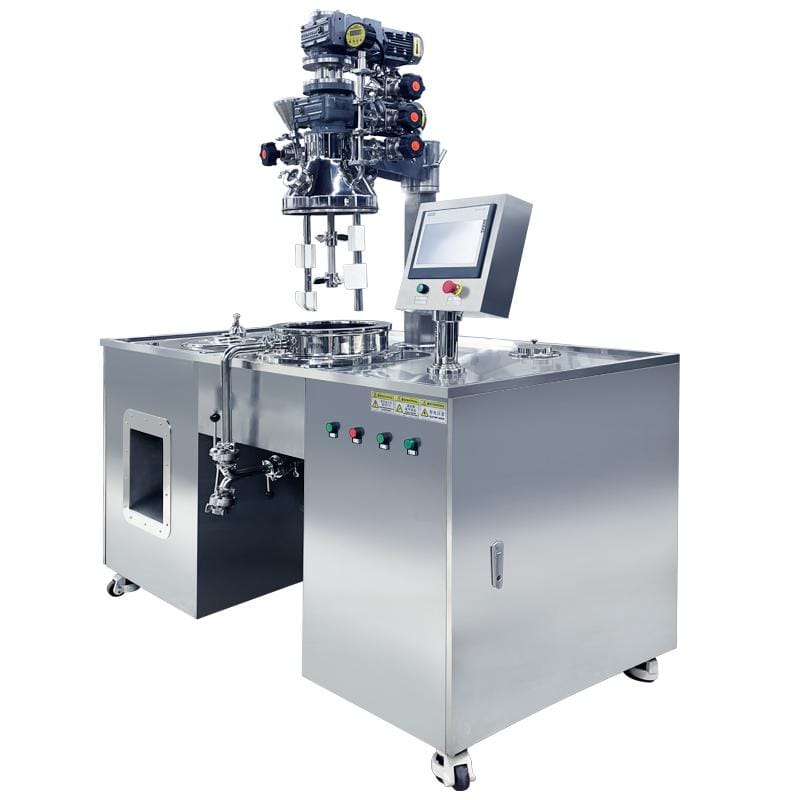
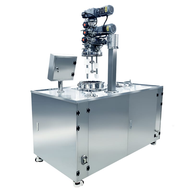
The 20L Laboratory Vacuum Emulsifying Mixer is a development and pilot-batch system for compatible creams, lotions, gels, ointments and related formulations. It combines counter-rotating agitation, PTFE scraping, bottom-entry homogenization and an external return circuit with steam jacket heating. Within the laboratory and pilot-scale emulsifying systems range, this model supports process evaluation before larger production trials.
| Total Capacity (L) | 30 | Vacuum Pump Brand | High-quality domestic/joint venture brands |
| Working Capacity (L) | 20 | Discharge Method | Electric/Manual Tilting Discharge / Bottom Valve Discharge (Optional Rotor Pump) / Bottom Valve Discharge (Optional Air Pressure Assist) / External Pump Transfer System |
| Min Batch Size (L) | 5 | Discharge Valves | Bottom Ball Valve |
| Structure Type | Triple Layer (with Jacket & Insulation) | Lid Lifting System | Hydraulic Lifting System (Automatic) |
| Contact Material | SUS316L Stainless Steel | Mechanical Seal Brand | Single Mechanical Seal (John Crane/EagleBurgmann Optional) / Double Mechanical Seal (EagleBurgmann) |
| Non-contact Material | SUS304 Stainless Steel | Tilting System | Electric Tilting |
| Surface Finish | Interior Mirror Polish (Ra ≤ 0.4 μm) & Exterior Satin/Matte Finish | Types of Upper Heads | Elliptical Head (2:1) / Hydraulic Lifting Head |
| Jacket Design Pressure (MPa) | 0.3 | Top Openings & Accessories | Vacuum Port / Vacuum Feeding Port / Powder Feeding Port / Liquid Inlet / Fragrance Addition Port / Manway / Sight Glass with Wiper / LED Inspection Light / CIP Spray Ball / Vent Filter / Vacuum Gauge / Pressure Sensor / Compressed Air Inlet |
| Main Tank Mixer Type | Counter-Rotating Anchor Agitator with Central Paddle | Motor Brand | SEW / ABB / Siemens / Top-Tier Chinese Brands (Optional) |
| Mixing Speed (rpm) | 0–63 rpm | vem_electrical_components | Schneider / ABB / Siemens / Omron / Fuji /Mitsubishi(Optional/Customizable) |
| Mixing Motor Power (kW) | 0.75 | Oil & Water Pot | Equipped with Oil Tank |
| Frequency Control | Variable Speed with VFD (Delta, Siemens, ABB, Schneider, Optional) | Oil & Water Pot Capacity (L) | Oil: 10L |
| Scraper System | Wall-Scraping PTFE Scrapers | Fully Raised Height (mm) | 2080 |
| Homogenizer Position | Bottom-entry Homogenizer | Voltage | Configurable to local grid (110V–480V, 50/60Hz, Single or 3-Phase) |
| Homogenizer Type | High Shear Stator-Rotor Homogenizer | Total Power (kW) | 3 |
| Homogenizer Power (kW) | 2.2 | Drive Type | Electric |
| Homogenizer Speed (rpm) | 0–3000 rpm (Variable Speed) | Installation Type | Mobile (Caster-Mounted) |
| Max Processing Viscosity (mPa·s / cP) | 50,000 | Automation Level | Fully Automatic |
| Heating Method | Electric Heating via Jacket / External Steam Heating (Optional) | Control System | PLC + HMI Touch Screen Control |
| Cooling System | Tap Water / Cooling Tower Circulation (Chilled Water / Glycol Circulation Optional) | PLC System | Siemens |
| Water Chiller | External Water Chiller Unit (Optional) | HMI / Touch Screen | Siemens |
| Temperature Control Accuracy | ±1°C | Machine Dimensions(L*W*H)mm | 1600*650*1650 |
| Vacuum Degree (MPa) | -0.09 | Machine Weight (kg) | 500 |
Product Gallery


Product Video
Product Overview
This machine provides a small-batch platform for investigating ingredient incorporation, emulsification, thermal processing and vacuum treatment. Its counter-rotating anchor and central paddle arrangement supplies bulk mixing, while the bottom rotor-stator homogenizer applies localized high shear and drives material through the external circulation route.
For cosmetic cream, lotion and skin-care development, the system can help evaluate formulation changes under documented processing conditions. A 10L oil preparation tank supports separate oil-phase work; no integrated water preparation pot is confirmed.
Selected ointment and pharmaceutical formulation duties may also be evaluated against product viscosity, material compatibility and cleaning requirements. The application description does not establish sterile processing, regulatory approval or suitability for every pharmaceutical product.
The confirmed heating arrangement uses external steam, with electric heating available as an alternative. Hydraulic head lifting provides vessel access, while electric tilting and the bottom ball valve offer different discharge arrangements. Siemens PLC and HMI provide the specified control platform.
The listed working range is 5–20L within a 30L total vessel capacity. Trials should assess the intended batch volume, circulation behavior and recoverable sample quantity rather than vessel capacity alone.
Machine Configuration
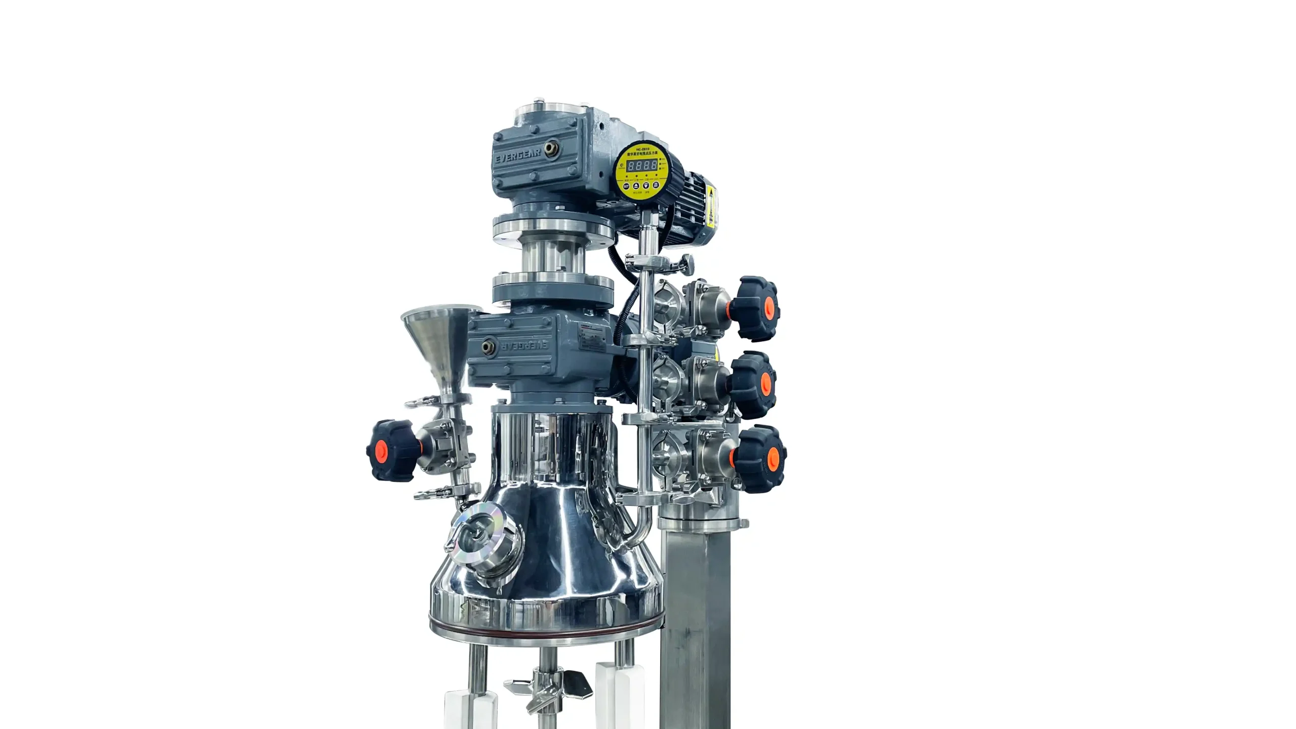
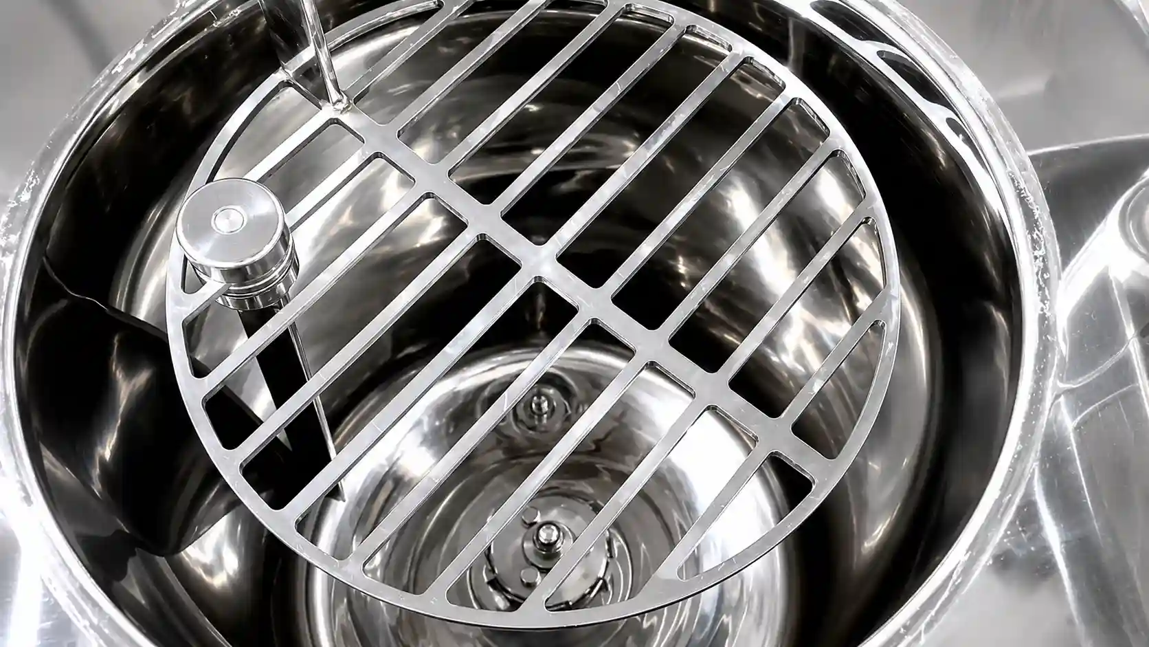
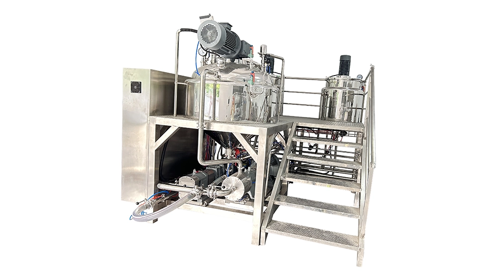
The main vessel combines a steam-heated jacket, insulation and a hydraulically lifting head. A counter-rotating anchor agitator with a central paddle and PTFE wall scrapers provides the specified bulk mixing arrangement.
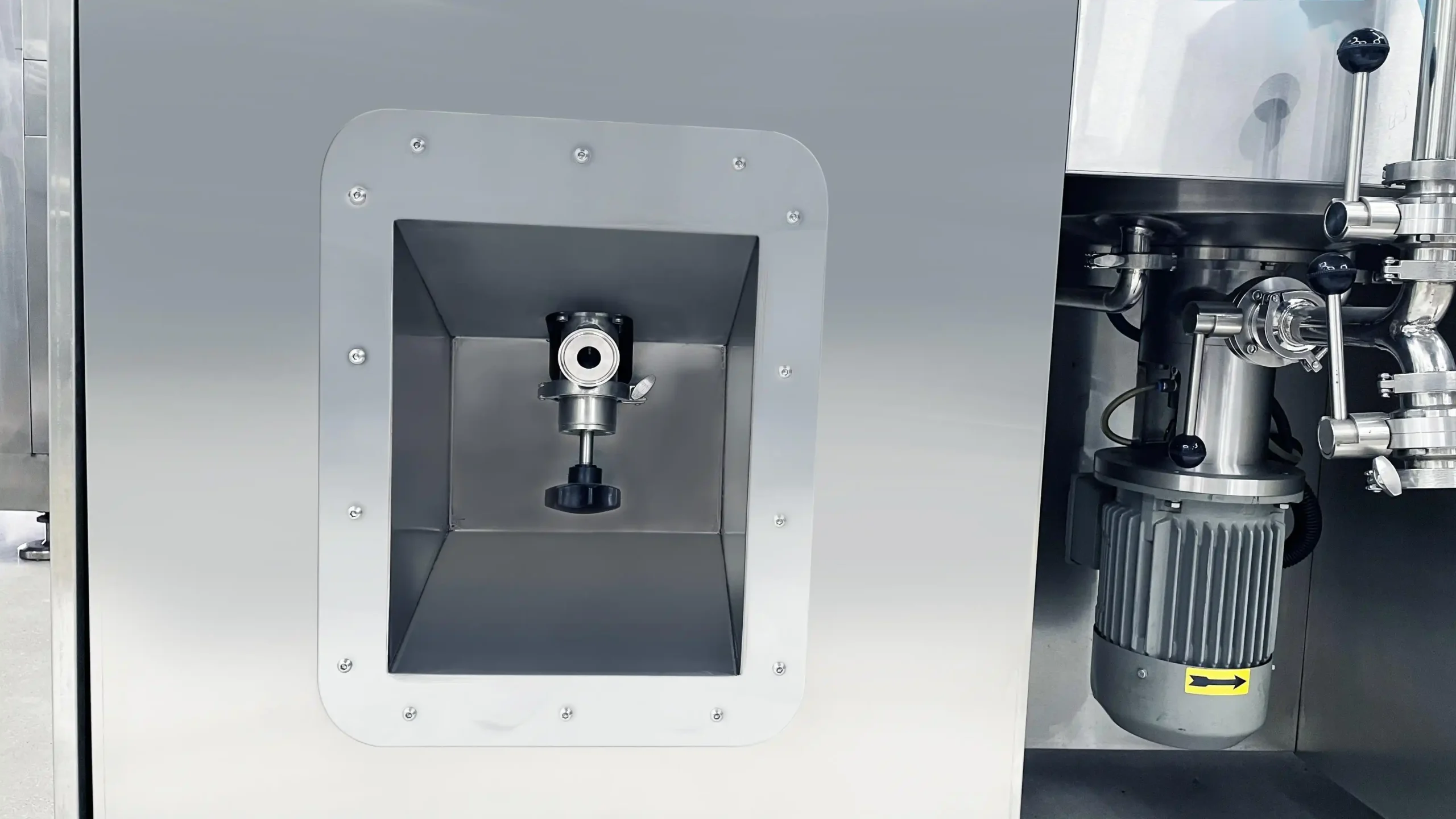
The bottom-entry rotor-stator homogenizer processes material and supplies conveying action into the external circulation route, which returns product to the main vessel. The final drawing should identify the outlet, return point, valves and cleaning route.
A separate 10L oil tank supports ingredient preparation. Siemens PLC and HMI coordinate the supplied functions through the agreed control program.
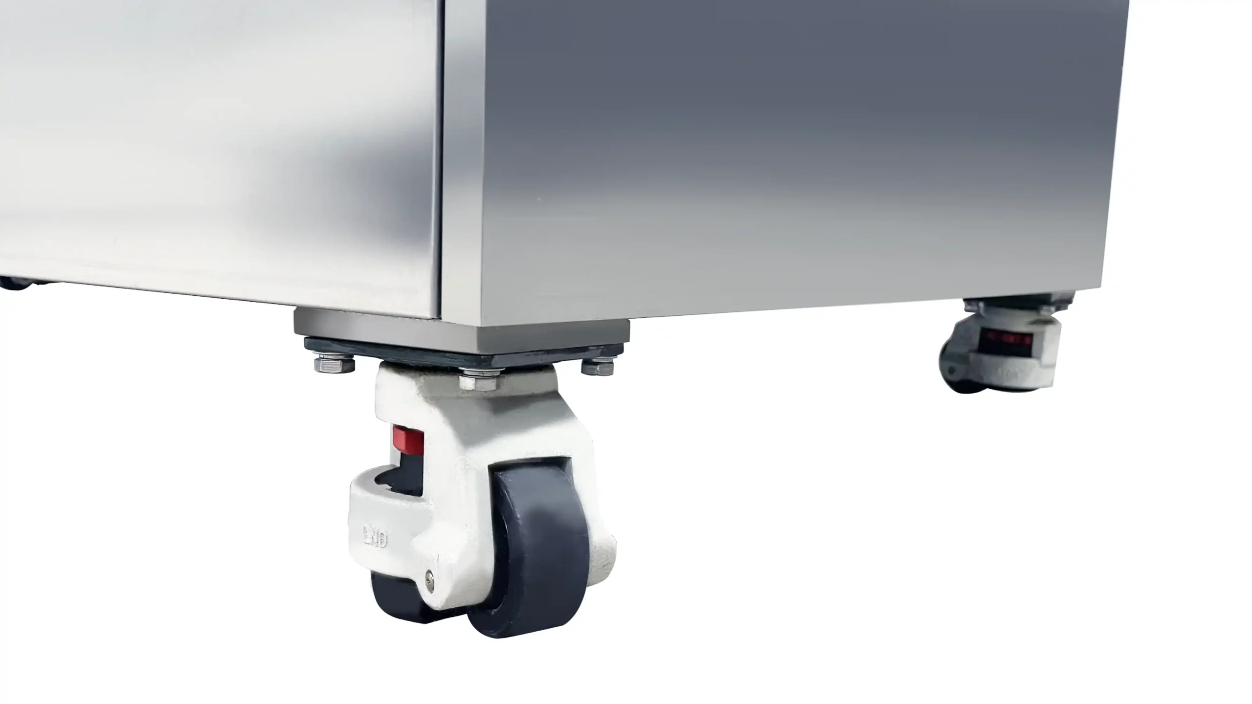
Electric tilting and a bottom ball valve provide the confirmed discharge arrangements; an external transfer pump is optional. The caster-mounted base supports planned repositioning under the approved handling procedure. Electric heating is an alternative configuration. Seal support, steam services, cooling connections and any external cleaning equipment require a defined supply schedule.
Key Features
- Counter-rotating agitation provides a defined bulk-mixing arrangement for formulation trials.
- PTFE wall scraping complements vessel circulation during thermal processing.
- Bottom-entry homogenization supplies localized high shear and external-circuit conveying action.
- The external return route allows circulation conditions to form part of the trial method.
- A separate oil tank supports formulation-specific phase preparation.
- Hydraulic head lifting provides access for approved inspection and cleaning tasks.
- Electric tilting and bottom-valve discharge accommodate different sample-recovery arrangements.
- Siemens PLC and HMI support the agreed processing functions and operator interface.
- Caster mounting supports controlled relocation between approved operating positions.
Applications
- Cosmetic Cream & Lotion, and Skin Care
- Hair Care, Personal Care & Body Wash
- Laboratory Mixing & Emulsifying Equipment
- Pharmaceutical & Ointment Products
- Sauce, Condiment & Food Paste
- Toothpaste & Oral Care Products
Recommended Machines



Working Principle
Development work begins with a defined formulation and trial objective. Ingredients requiring separate oil-phase preparation can be handled in the supplied oil tank, while any separately prepared water phase needs an external arrangement.
After charging, the anchor and central paddle operate in the supplied counter-rotating arrangement. PTFE scrapers act along the vessel wall, while the jacket transfers heat from the selected steam service into the batch. Operating settings follow the ingredient sequence and permitted thermal conditions.
Material entering the bottom rotor-stator homogenizer experiences localized shear. The homogenizing head also provides the conveying action that moves material through the external circulation path and back into the main vessel. Actual circulation depends on the working head, product and pipework; rpm alone does not establish flow or pass count.
Vacuum is applied at the stages defined by the trial method. The operator or supplied program coordinates ingredient addition, agitation, homogenization and thermal conditions according to the agreed control functions.
Cooling proceeds through the selected jacket-water service where required. Heat-sensitive ingredients may enter during a separately defined finishing stage.
Once the sample meets the trial endpoint, the machine is brought to the approved discharge condition. Product leaves through the bottom ball valve or electric tilting arrangement, with an external transfer pump optional. The head-lifting and tilting sequences must follow the manufacturer’s pressure-equalization and operating procedures.
Optional Upgrades & Configurations
| Warranty | 24 Months | Payment Terms | 40% T/T Deposit, 60% Balance Before Shipment (Alibaba Trade Assurance Available) |
| Lead Time | 15–20 Working Days | Packaging | Standard Export Fumigation-Free Wooden Case |
After-Sales & Technical Support
🔧 Common Problems
Possible observable symptoms include inconsistent samples, visible agglomerates, uneven product movement, excessive foam, retained air, unexpected viscosity changes or differences between repeated trials. Circulation-related observations may include weak return flow, intermittent movement or a meaningful quantity of retained material after discharge. Operators may also observe slow heating, differing temperature readings, unstable vacuum indications, abnormal agitator or homogenizer noise, drive trips, seal leakage or residue remaining after cleaning. Access-related observations may include irregular hydraulic lifting or difficulty completing the intended tilting movement. These are potential observations rather than confirmed defects. Record the batch quantity, formulation version, ingredient stage, settings and utility conditions when investigating a symptom.
🛠 Troubleshooting
Problem: Repeated trials produce different sample conditions. Possible Cause: Charge quantity, ingredient preparation, settings or sampling conditions differ. Recommended Solution: Compare the complete trial records before changing the formulation or replacing components.Problem: External return flow becomes weak or intermittent. Possible Cause: Valve routing, operating level, viscosity or a restriction affects the circuit. Recommended Solution: Review the approved route and product conditions. Stop and isolate the equipment before inspecting for restrictions.Problem: Vacuum does not reach the intended condition. Possible Cause: An open vent, incorrectly seated connection, product foaming or a vacuum-system fault. Recommended Solution: Check accessible settings and the approved valve arrangement. Arrange qualified sealing and vacuum-system inspection.Problem: The batch heats more slowly than expected. Possible Cause: Steam conditions, condensate removal or batch conditions differ from the approved arrangement. Recommended Solution: Review the utility indications and trial record. Have qualified personnel inspect the steam system before changing limits.Problem: The homogenizer makes abnormal noise or vibrates. Possible Cause: Inadequate coverage, restricted flow, deposits or a mechanical fault. Recommended Solution: Stop and isolate the affected assembly. Obtain qualified inspection before restarting.Problem: Lifting or tilting movement becomes irregular. Possible Cause: An obstruction or a fault in the relevant movement system. Recommended Solution: Stop the movement and follow the approved support and isolation procedure before service inspection.
🧼 Cleaning Method
1. Recover the remaining product through the approved valve or tilting arrangement. 2. Stop thermal input according to the operating procedure. 3. Bring the vessel to the safe temperature specified for cleaning access. 4. Equalize vessel pressure through the approved method before opening the head. 5. Raise the head according to the manufacturer's operating procedure. 6. Secure the raised assembly using the approved support method. 7. Isolate energy sources under the site's lockout procedure before manual access. 8. Configure the approved cleaning route through the vessel and external circuit. 9. Pre-rinse product-contact surfaces with a medium suitable for the residue. 10. Apply the approved cleaning agent under the specified cleaning conditions. 11. Clean the agitator, central paddle and scraper attachments through the approved access method. 12. Clean the homogenizer and circulation route according to their instructions. 13. Clean the oil tank according to its individual procedure. 14. Clean designated detachable ball-valve components separately where required. 15. Rinse until the specified cleaning-agent acceptance criteria are met. 16. Sanitize the system when the validated product-changeover procedure requires it. 17. Inspect accessible surfaces before reassembly and release.
📋 Maintenance
1. Isolate the machine under the approved lockout procedure before preventive maintenance. 2. Equalize vessel pressure before opening service connections. 3. Support the raised head using the manufacturer's approved method. 4. Inspect the anchor and central paddle for visible damage or deposits. 5. Examine PTFE scraper blades for wear or deformation. 6. Inspect the rotor-stator assembly during approved service access. 7. Check installed mechanical seals for leakage or deterioration. 8. Inspect circulation connections and supports for visible damage. 9. Examine the bottom ball-valve sealing components according to their instructions. 10. Inspect accessible hydraulic hoses and connections for deterioration. 11. Service the electric tilting assembly according to its component documentation. 12. Service the vacuum pump according to the installed pump manufacturer's schedule. 13. Inspect steam and cooling connections through the approved utility-maintenance procedure. 14. Check the caster and restraint arrangement for deterioration. 15. Arrange qualified inspection of electrical terminals and protective devices. 16. Verify supplied stop functions and operating protections through the approved test method. 17. Record service findings against the machine serial number and operating history.
⚙️ Installation
1. Review the final vessel, circulation and movement drawings before preparing the site. 2. Verify the delivery route against the transport envelope and handling requirements. 3. Obtain approval of the floor for the complete operating loads. 4. Inspect the delivered assembly for visible transport damage. 5. Position the machine using the manufacturer's approved handling method. 6. Secure the caster-mounted base at its designated operating location. 7. Confirm hydraulic head-lifting clearance against the final drawing. 8. Confirm the electric tilting envelope and receiving-container position. 9. Connect the external circulation route according to the approved drawing. 10. Install the engineered steam supply arrangement. 11. Connect the specified condensate return or drainage route. 12. Connect the selected cooling-water services. 13. Connect required vacuum-pump and mechanical-seal support services. 14. Arrange electrical connection by qualified personnel using the final load and wiring schedule. 15. Verify protective earthing before electrical commissioning. 16. Commission hydraulic lifting and electric tilting under the approved procedure. 17. Verify the supplied control functions and operating protections. 18. Perform the approved liquid test of mixing, circulation and connected services. 19. Document the representative-product trial against the agreed acceptance criteria before routine use.
🔩 Spare Parts
Why Choose This Machine
- Development-scale processing: The 20L working capacity supports formulation and process evaluation without committing to a production-size batch, while allowing more material than very small laboratory trials.
- Complementary mixing functions: Counter-rotating agitation, scraping and bottom homogenization provide different processing actions that can be evaluated against the formulation objective.
- Defined circulation study: The external return route allows the team to examine circulation as part of the method, provided its geometry and operating conditions are documented.
- Separate oil-phase preparation: The supplied oil tank supports recipes requiring independently prepared oil ingredients without implying a complete two-pot preparation system.
- Accessible changeover: Hydraulic opening and the confirmed discharge arrangements support inspection and sample recovery under the approved procedure.
- Structured production evaluation: The system can help identify process sensitivities and required functions for later equipment selection, without treating laboratory results as verified production performance.
Frequently Asked Questions
Installation Requirements
The listed machine weight is 500 kg. Assess the floor and caster loading for the complete operating arrangement, including product, the oil tank and connected services. Define a level operating location and the approved method of securing the mobile assembly.
Provide an engineered external steam supply matched to the jacket's approved operating limits. Include isolation, regulation, protection and condensate handling in the installation scope. The 0.3 MPa jacket design pressure is not a main-vessel positive-pressure rating.
Provide the selected cooling-water service and approved heating-to-cooling changeover arrangement. Confirm vacuum-pump and mechanical-seal support services from the installed component documentation.
Obtain the final electrical load schedule for the motors, vacuum pump, hydraulic lifting, electric tilting and controls. Do not use the unverified 3 kW total-power entry to size the electrical supply. An electric-heating alternative requires its own load assessment.
Provide suitable cleaning-water access and drainage. Compressed air is only required for functions explicitly included in the final equipment schedule. Confirm safe disconnection and reconnection of services before relocating the machine.
Related Articles


Technical Buyer's Handbook & Deep Insight
Ready to Get a Quote?
Contact our team directly for pricing, customization options, and delivery timelines.
💬 WhatsApp Us NowGet Your Download Link
Please fill in your details and we'll send the download link to your email.